
Post Project 61: KaraOkay Microphone Amplifier
The two opams are biased at 0.5 Vcc with the help of voltage divider R19-R20.
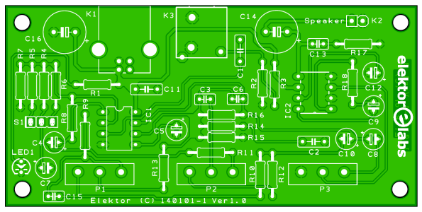
The circuit is built on the printed circuit board shown here, which was designed for compactness and low noise. The tone and volume controls P1, P2 and P3 as well as microphone input and USB supply connectors K3 and K1 are all on the PCB, avoiding wiring that would make the circuit susceptible to hum and noise. The photos illustrate a suggested method of housing the amplifier board in a compact, strong but not beer resistant, ABS case.
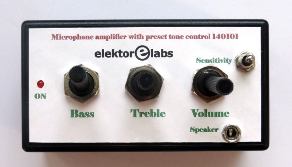
ABS case (not beer resistance!)
The circuit is built on the printed circuit board shown here, which was designed for compactness and low noise. The tone and volume controls P1, P2 and P3 as well as microphone input and USB supply connectors K3 and K1 are all on the PCB, avoiding wiring that would make the circuit susceptible to hum and noise. The photos illustrate a suggested method of housing the amplifier board in a compact, strong but not beer resistant, ABS case.
Component List
Resistors
R1 = 330Ω
R2 = 1MΩ
R3, R4, R9, R10, R19, R20 = 10kΩ
R5 = 470Ω
R11, R12 = 4.7kΩ
R6 = 2.2kΩ
R7 = 27kΩ
R8 = 100kΩ
R13 = 12kΩ
R14 = 3.3kΩ
R15 = 270kΩ
R16 = 2.2MΩ
R17 = 10Ω
R18 = 1.2kΩ (see text)
P1 = 100kΩ lin. potentiometer
P2 = 470kΩ lin. potentiometer
P3 = 10kΩ log. potentiometer
Capacitors
C1, C11 = 100nF 50V, X7R, 0.2’’ pitch
C2 = 2.2nF 50V, 0.1’’ pitch
C3 = 4.7nF 100V, X7R, 0.1’’ pitch
C4, C10 = 4.7μF, 50 V, 2 mm pitch, 5x11 mm
C5 = 1μF 50V, 2mm pitch
C6 = 100pF 50V, Y5P, 0.1’’ pitch
C7, C8, C9, C12 = 10μF 50V, 2mm pitch, 5x11 mm
C13, C15 = 47nF 50V, X7R, 0.1’’ pitch
C14, C16 = 220μF, 50V, 5mm pitch
Semiconductors
IC1 = TLC272 or OPA2350PA
IC2 = LM386
LED1 = LED, red, 3mm
Miscellaneous
K1 = USB type-B receptacle, right angle
K2, S1 = SIL pinheader, 0.1’’ pitch
K3 = 3.5-mm stereo jack socket, PCB mount
S1 = switch, SPDT, center-off
IC socket, DIP-8
Casing, e.g. Bud Industries CU-793, Digikey #377-1167-ND
PCB # 140101
Read full article
Hide full article
Discussion (0 comments)