
Magnetic Levitation the Easy Way
on
Two similar DIY magnetic levitation projects from designer Peter Neufeld are presented on the Elektor Labs pages, and in both cases, a Lego figure that floats in the air. Both work on the same principle: the strength of a magnetic field between an electromagnet and a neodymium magnet is measured with a Hall-sensor and the electromagnet is controlled depending on this measured value. The difference between the projects is in the control circuit: the first is “hardware only” and uses an analog comparator, while in the second a M5Stack Atom ESP32 Pico microcontroller module is used.
On Wikipedia, levitation is described as “the process by which an object is held aloft, without mechanical support, in a stable position.” This is accomplished by applying an upward force to this object, equal to the Earth’s gravitational force. Electromagnetic force is one of the options if you want to design an electronic levitation project. In theory, a construction consisting of two permanent magnets would do the trick too, but because in the real world, there are all kinds of disturbing influences that can upset this unstable balance, in practice electromagnets are used. A control circuit can then vary the strength of the magnetic field to keep the floating object in place. This requires some kind of feedback on the position of the floating object, and in the two projects presented on the Elektor Labs pages, a Hall sensor is used to measure the strength of the magnetic field between an electromagnet (in a fixed position, attached to a frame) and a permanent magnet that “floats” under it. The output voltage of this sensor is used as a measure for the distance between the two. The term “control circuit” often evokes memories of elaborate, rather complex calculations and circuits needed to realise a stable control system, but Peter Neufeld’s projects show that it does not always has to be this complicated.
Levitation projects are always eye-catchers. Somehow it is always fascinating to see that an object can just float in the air. It looks magical, as if the laws of gravity no longer apply to the floating object, which is, of course, not the case. I found it quite extraordinary that it could de done with so little electronics. Most other DIY magnetic levitation projects I’d seen before Peter’s projects looked much more difficult to build, often with self-made coils, and requiring high currents. Anyway, the videos that Peter posted proved that it should be possible, even though he already states that it takes some precision and dexterity to get the calibration right. One way to find out if it works: just give it a try!
This article covers one of the projects, called “easy way”, and it’s the one with the analog comparator to control the electromagnet. The article will mainly be focused on how the levitation works. In a following article, the version with the M5Stack Atom ESP32 Pico will be covered, with more focus on the cosmetics to create a nice looking levitation gadget.
Hardware for the Analog Version
The schematic diagram in Figure 1 shows that only very simple hardware is needed to build this project.
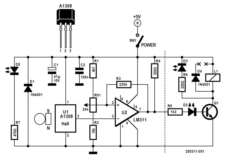
L1 depicts the coil of a relay, with its switching mechanism removed. It is part of a standard relay board (which will be discussed in the following section), that is attached to a frame with the core pointing downwards, the levitated object (with a permanent magnet) will hover under this coil. R6 and LED3 replace flyback diode D4 on this PCB and will serve as optical indication during calibration of the levitation circuit. Hall sensor U1 is mounted on the core and measures the magnetic field between L1 and the floating object, its output is connected to the inverting input of comparator U2, an LM311. The non-inverting input of U2 is connected to the wiper of preset trimmer RV1, which is used for adjustment of the control circuit, while R3 provides a small hysteresis to the comparator. The output of the comparator switches the coil on when voltage at the output of the Hall sensor is lower than the preset level on the wiper of RV1.
LED D5 is the power-on indication and SW1 the power switch. D1 is a so-called crowbar diode that protects the circuit if the supply voltage is accidentally connected the wrong way round.
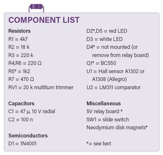
Getting the (Right) Components
Most parts in the schematic and the bill of materials are standard components, only the A1302 or A1308 Hall sensors from Allegro turned out to be a bit more difficult to source. But the cheaper and more widely available sensors like the SS49 failed to work in the early prototypes of Peter’s levitation projects, probably because the output signal does not react quickly enough when the magnetic field varies, but this has not been investigated further.
Surprisingly, the most tricky part to get was the relay board that is used for the electromagnet. These modules are readily available on the internet in dozens of maker and Arduino web shops and it shouldn’t be any problem to find and buy them. Peter had tested boards marked HW-482 with JQC-3FF-S-Z and JQC3F-05VDC types of relays. I (re-)learned a very important lesson when shopping on the internet: never trust photos in web shops! I looked at the photos that the designer posted and found exactly the same board on Amazon. I received modules with the board marked HW-307, carrying a relay with type number FL-3FF-S-Z. They work as described and promised in the shop, i.e. a 5 V SPDT relay boards with driver transistor, flyback diode and indicator LEDs. But the transistor on this board is an PNP type, as opposed to the NPN on the relay boards Peter tested. I gave it a try anyway, except for the type and brand the relay looked very similar to the one used in the original project; as turned out later, also on the inside. After all, for this project, the coil and core of the relay are the most important parts.
For the magnets, a stack of two or three disk-shaped neodymium magnets with a diameter of 8 to 12 mm and 2 to 3 mm thickness were used. The size and number of magnets needed will also depend on the Lego figure or any other load you want to attach to them. I started with a stack of two magnets only, both 10 mm diameter and 2 mm height, and I would recommend to start experimenting with such a simple object to get the feeling how to adjust the control circuit. It may be a good idea to mark the top of the stack with a permanent marker or piece of tape to keep the orientation right. Once you get that working, you can continue with other magnets and adding objects (like a Lego figure). Of course, there are limits to the size and weight of the load that can levitated with this hardware. In this article, the term “magnet(s)” will refer to the complete load, i.e., the stack of magnets plus optional load.
Assembly
There is no PCB design for this project, but it is easy to build with a piece of Veroboard or even on a breadboard. Figure 2 shows an overview of the setup of the original prototype.
When constructing the hardware for this project, start by removing the 3-way terminal block from the relay board to get more space to work on the relay. Take a close look at Peter’s photographs in Figure 3 to see what to do with the relay, essentially: remove its cover and most of the switching mechanism, only the coil and core are used. Shorten the U-shaped core to a J-shape to prevent magnetic field shortout. Some kind of small grinding disk on a Dremel tool may come in handy to cut metal parts.
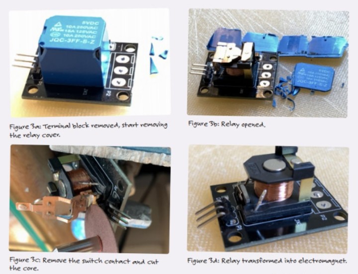
Whatever type of board you have, the flyback diode D4 for the relay must be removed and replaced by adding R6 and white LED D3. With the relay board Peter bought, the rightmost part of the schematic in Figure 1 is finished then, including Q1, R5 and D2 that are already installed on the PCB. In my case, I only kept the relay coil, removed all other components and rebuilt this part of the circuit with through-hole parts. A BC550 for Q1 or any other standard NPN-transistor will do fine for controlling the relay coil. In hindsight, with the boards I received, it would have made more sense to just buy the relay, but these small, mass-produced relay modules are probably cheaper than buying a separate relay only.
Please note that the references of the parts on the relay board in the schematic in (L1, R5, D2 Q1 and D4) do not correspond to component references on the PCB. It will not be too difficult to identify the flyback diode D4 that must be removed.
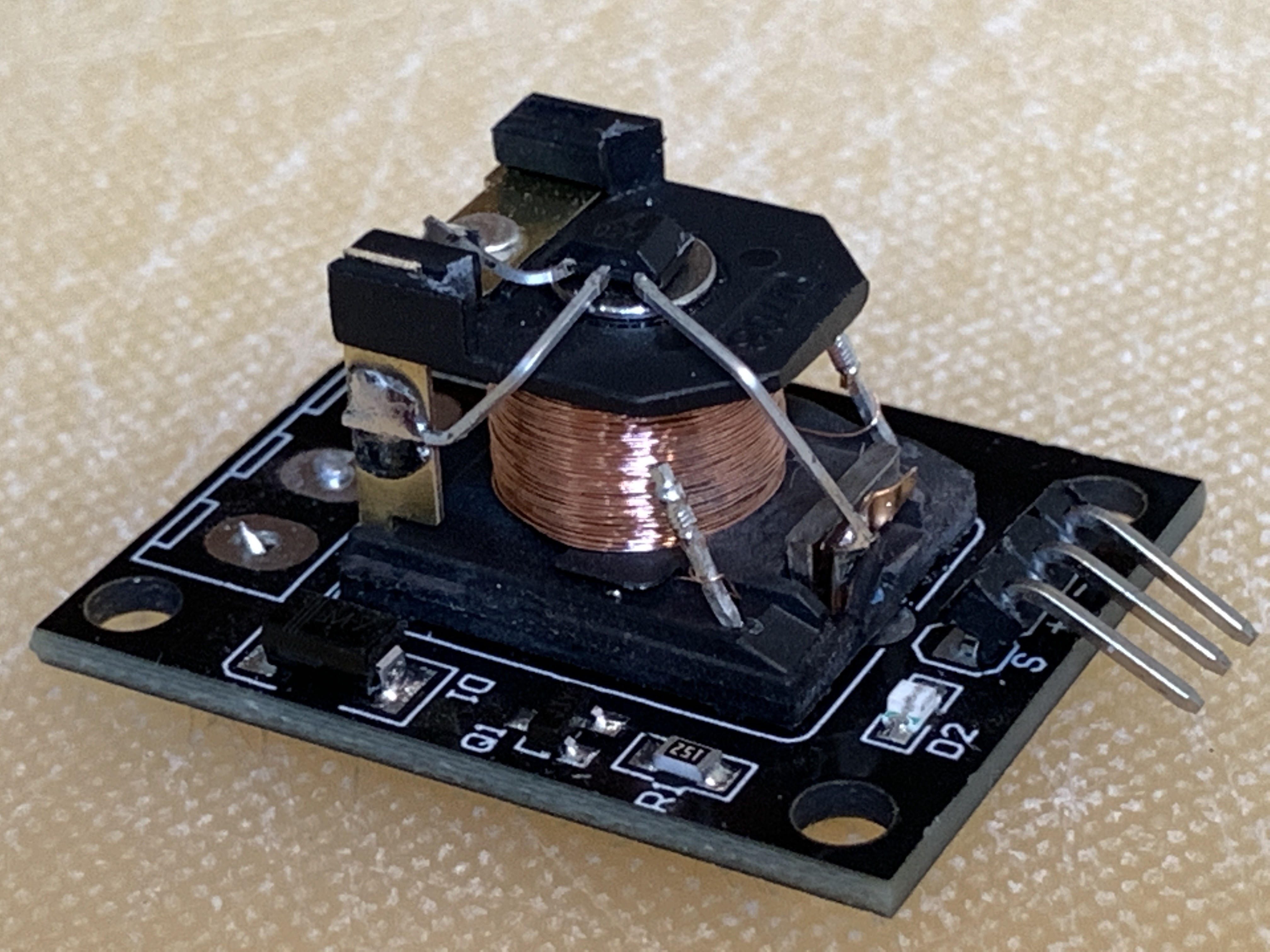
The Hall sensor is mounted directly on the core of the coil, align it to the center of the core’s surface as shown in Figure 4. Glue a thin piece of plastic over the sensor and its pins to prevent short circuits of the power supply when the magnet gets pulled up to the core.
Building the rest of the circuit using the modified relay board and an additional piece of Veroboard will not be too difficult. But note that the wiring of the coil and orientation of the permanent magnet and the Hall-sensor are very important to get the magnetic levitation working:
- When the permanent magnet comes closer to the coil and Hall sensor, the output voltage of the sensor must increase.
- When the coil is switched on, its magnetic field must attract the magnet.
If one of these conditions is not met (or both), it will not work. The first condition is easily checked by measuring the output voltage of the Hall sensor using a multimeter; simply flip the magnet if the voltage lowers when it approaches the sensor. And the second one … I could feel the force between the powered coil and magnet, that seemed to be okay.
It looked like the control circuit I had built was working correctly, since both LEDs were lit when they should be: D2 when the coil is switched on, D3 flashed when the coil switched off as the magnet came closer the coil. It should be a matter of trimming RV1 to get the correct voltage setting on the non-inverting input of the comparator to get the magnet attached to a Lego figure (or any other kind of small weight) hovering like in the video. But my efforts were in vain: the magnet just slammed onto the coil or fell down on the table.
Then I remembered the second condition for the levitation to work. I could definitely feel that the magnet — when I was holding it between my fingers — was attracted to the coil when it was powered. That should be OK too. Or not?
If Everything Fails, Read the Manual (or Think, or Read Again)
First, I checked the strength of magnetic field of the coil. I was surprised to notice that its electromagnetic force appeared to be almost negligible: directly powered with a 5 V supply, it could hardly pick up the tiniest iron object. Not the kind of force you would expect to lift anything, let alone a force strong enough to make a relatively heavy load like a magnet and an object attached to it float. But here I overlooked something very important: even when the coil is not powered, there is still the static magnetic force between the permanent magnet of the load and the metal core of the coil. This force is much stronger than the electromagnetic force of the coil. So the trick is: when the permanent magnet nears the core, there is a point where the static force just isn’t strong enough to pull the magnet towards the core. This is where the additional electromagnetic field comes in: the coil only adds a small force to the static field, just strong enough to pull the magnet up. The magnetic field measured by the Hall sensor increases (and thus its output voltage) as the magnet comes closer to the core, switching off the coil (with correct adjustment of RV1!) and preventing the magnet to be pulled completely towards the core. Gravity then pulls the magnet down, lowering the field measured by the sensor, switching the coil on again — and so on.
Since the electromagnetic field is very weak compared to the static magnetic field, it is difficult to determine if the powered coil attracts or repels the magnet. I used an old-fashioned compass to confirm if the orientation of the electromagnetic field was correct to meet the second condition for hovering. When I re-read Peter’s documentation, I saw that he mentioned a simple solution to find the right orientation of the coil: the output voltage of the Hall sensor doesn’t only increase when the permanent magnet comes closer, but also when the coil is powered (e.g. by connecting the collector of Q1 to GND). You may need to either swap the connections of the coil and LED D3 to get it right.
Adjustment
As pointed out earlier, it takes precision and dexterity to find the point where the load will hover, somewhere in the range of 10 mm to 15 mm distance between coil and load. Peter describes a procedure of using a stack of Post-It notes to get the distance right for calibration, but for some reason — my lack of precision and dexterity, I guess — this didn’t work for me. My trick was to put the magnet on my hand, very slowly lifting it towards the coil until I could feel the magnetic force picking it up. If the coil switches off before that point is reached, adjust RV1 for a higher threshold on the non-inverting input of the comparator, or to a lower level if it doesn’t switch off before the magnet is pulled up to the core. The white LED will light briefly when the coil is switched off, adjust the potentiometer to the point where this LED looks to be continuously lit (in fact: it will be flashing at the control frequency of the magnet). At first, you’ll end up with the magnet stuck to the core, but once you get the hang of it, you’ll notice that it gets increasingly easy to get the calibration right for other loads. With my setup, I could even hear the switching of the control circuit when the setting is (almost) correct. And yes: it may take some time before you get it right, but you can do it!
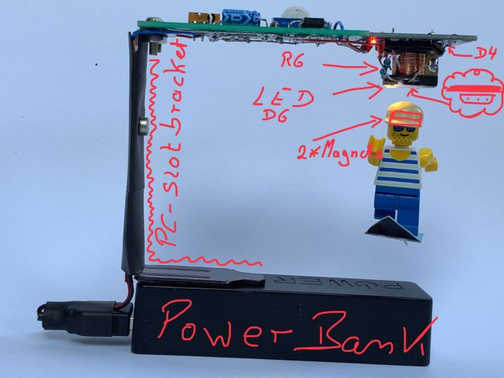
My first intention was to build a prototype that looked at least as good as the one by the author, but with all the changes I had to make to get it working, I completely failed in that respect, as can be seen in Figure 5.
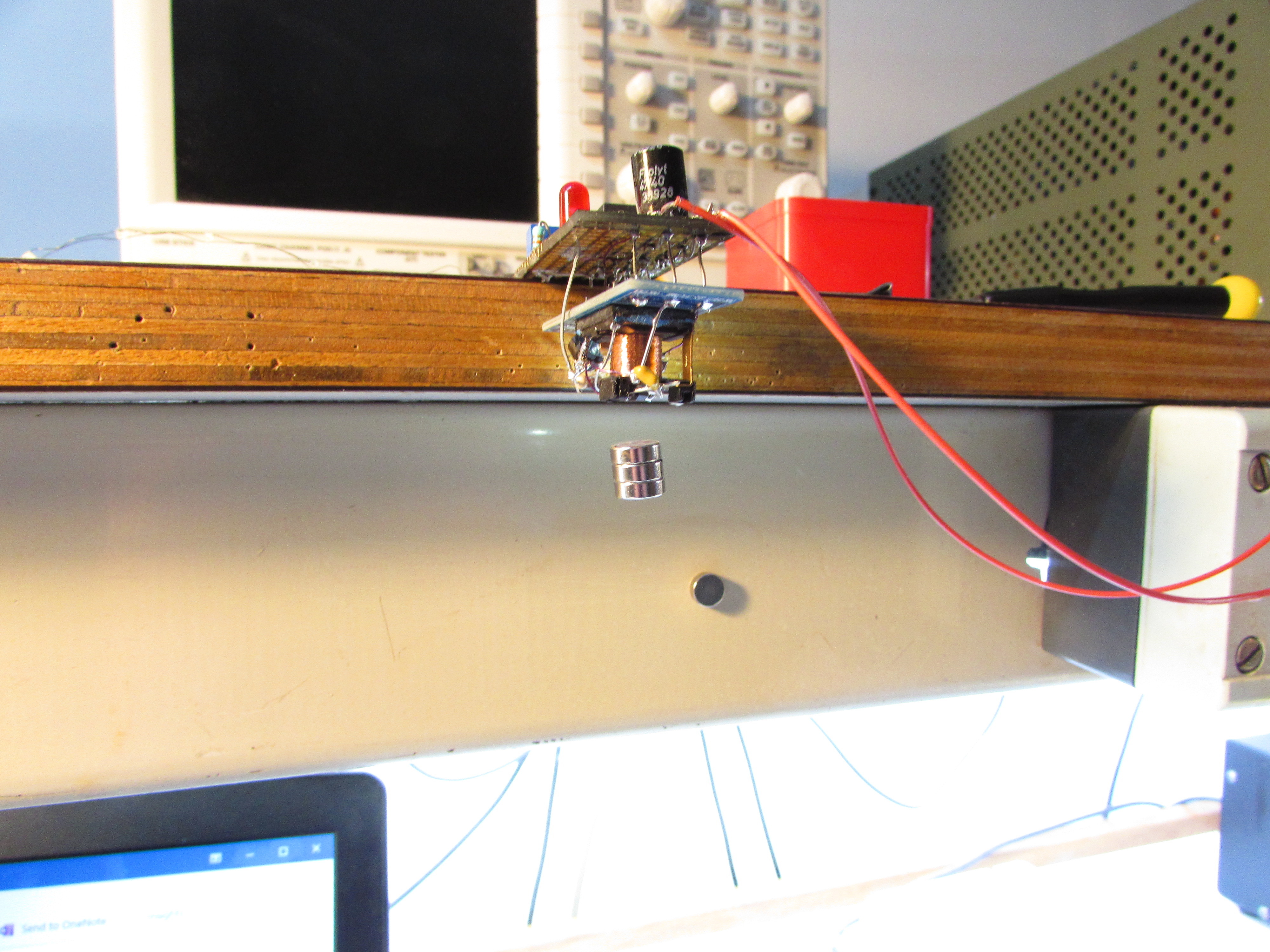
But my main goal was achieved: I got the magnetic levitation working! And maybe some day, when I run out of ideas what to do with my spare time ... But I’ll put more effort in cosmetics of the second part that will follow in the next levitation project that Peter Neufeld has designed, the Digital Solution. With the lessons learned from this “simple” analog setup, most pitfalls encountered in the analog version can be avoided and the second project should be easier to do, leaving more time to make the hardware look good too!
Questions About the Article or Magnetic Levitation?
Do you have technical questions or comments about this article or the topic of magnetic levitation? Feel free to contact the editor at luc.lemmens@elektor.com!
Discussion (1 comment)