
Magnetic Levitation the Digital Way
on
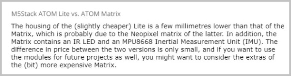
The title of the first article in this series, “Magnetic Levitation the Easy Way,” might have suggested that we will now discuss a much more complex way to accomplish levitation, but that is not the case. In this second installment of the levitation project, the analog comparator of the first design is replaced by either an M5Stack ATOM Lite or ATOM Matrix, small ESP32-based modules (refer to the textbox “M5Stack” nearby) for measuring the Hall sensor’s output voltage and controlling the coil. In fact, not counting all components inside the M5Stack module, you need far fewer parts to build this digital version compared to the analog circuit. The funny thing is that, to some of our readers, using a microcontroller is the easy way, while others will complain and ask why we use the overkill of an ESP32 module when basically a simple LM311 can do the trick too. It is hard to please everyone; therefore, in this case, we decided to present both options.
Any ESP32 module other than an M5Stack ATOM would do for this project too. For one of the versions of the prototype (see below), a push button to adjust the levitation control loop (already present in the ATOM modules) will come in handy.
The M5Stack modules were chosen because they are affordable, extremely small, and well protected against short circuits in their plastic enclosures. All I/Os needed for this project are easily accessible on the SIL sockets at the bottom of the ATOMs. The Neopixel LEDs present in the M5Stack ATOM Matrix model are only used for cosmetics of course, they don’t contribute to the levitation process, so for this project the Lite model, with only one Neopixel LED, can also be used.
During a discussion I had with Peter when I started writing this article, he came up with the idea to add a trimmer instead of using the push button to do the adjustment of the control loop; he eventually built and tested this solution too. This “extra version” is discussed on his web pages [4] and in this article.
Magnetic Levitation Hardware, Original Version
As the schematic in Figure 1 shows, the hardware used is roughly the same as in the analog version. The modification of the relay board is mainly identical to Part 1, the most important difference is that the Hall sensor is now powered at 3.3 V, from the internal voltage regulator of the ATOM module.
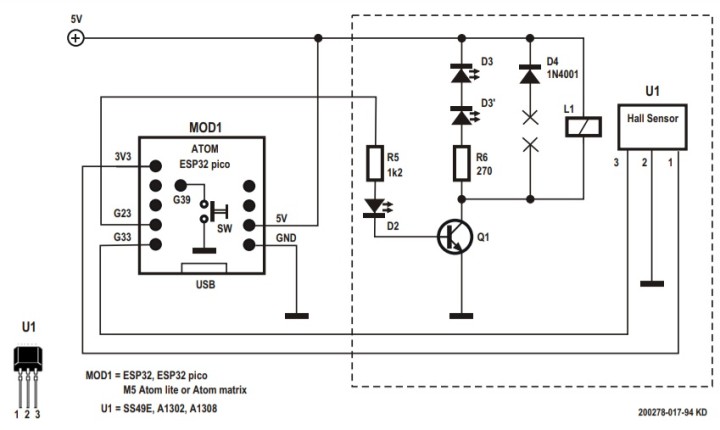
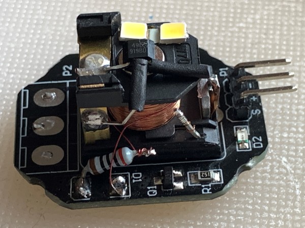
Figure 2 shows the resulting electromagnet with the Hall sensor mounted on its core. Here the flyback diode for the relay is replaced by two white LEDs that are used as “spot lights” to illuminate the levitated object. One LED — as in the analog solution — would do too. However, apparently the two-LED setup performs better where stability of the hovering object is concerned. It is important to keep the flyback current through the LEDs low, as a higher current sustains the electromagnetic field too long, even when the transistor is switched off. This additional field could prevent a good control loop and then destabilizes the hovering of the load. But the LEDs and the resistor are absolutely necessary and have to replace the original diode, as they limit the induction voltage at the relay transistor to a harmless level of below 50 V and ensure the correct short switching pulses. Two white LEDs with a 220 to 330 Ω series resistor did the job very well.
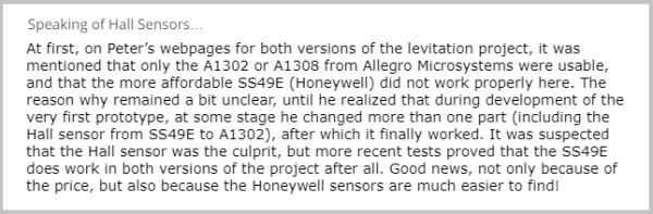
Of course, the 3.3 V supply voltage also keeps the sensor’s output level between 0 V and 3.3 V, not exceeding the maximum input voltage of the M5Stack ATOM’s ADC. Note that this supply voltage is not according to the specs of most Hall sensors (see the textbox “Speaking of Hall Sensors" nearby). Looking at the datasheets, the minimum supply voltage for the A1302/A1308 should be 4.5 V, but apparently, they do work at lower voltage (that is: for this project!), and this avoids the need of a voltage divider to stay within the input limits of the ADC. However, there is one downside: apparently the sensor’s output voltage already clips at a lower magnetic field strength with this supply voltage, and this limits the weight of the load that can be levitated. And it is even a limiting factor for the SS49E, although this Hall sensor is specified for a minimum supply voltage of 2.6 V.
The circuit is powered with 5 V, either via the USB-C connector, its Grove port connector or the SIL-socket on the bottom side of the M5Stack ATOM.
Magnetic Levitation Software
The algorithm in the Arduino sketch to control the levitation is basically very simple: the ESP32’s ADC measures the output voltage of the Hall sensor, compares it to a trigger level (with some hysteresis) and switches the coil on or off, so the software mimics the LM311 comparator of the first setup. In the first example on Peter’s webpage (MagLev_1.INO), the trigger level and the hysteresis are defined as constant values in the sketch and must be tuned to the load you are using. It can take some time to find the correct value for the trigger level, as it depends on the load and of course on the size and strength of the permanent magnet you are using.
The source code of this first sketch is more like a simple demonstration of the control algorithm, as you have to recompile and upload it every time you change one of these constants, which is not very practical. The second sketch uses the integrated push button of the M5Stack ATOM to change the threshold for the Hall sensor output voltage during run-time. When this program starts, the level is set to a pre-defined value, which can be lowered by pressing the M5Stack ATOM’s push button until the load is hovering under the electromagnet. With the current version of this sketch (MagLev_2.INO) and with only a single user defined push button to control the calibration, the threshold can only be decremented. If it is set too low, the M5Stack must be reset and the calibration process must be performed all over again. The new setting can be tracked in the serial monitor of the Arduino IDE, and when the correct threshold value is determined, it can be entered in the sketch’s source code, which can then be recompiled and uploaded to the M5Stack ATOM module. And then of course, as long as the load isn’t changed, no further adjustment is needed when the hardware is reset or powered on again.
Looking at the source code of this sketch, you’ll notice that there are several lines with different default settings for the threshold commented out. Of course, every load has its threshold and different types of Hall sensors may have their own optimal threshold setting. But there are even differences when the M5Stack ATOM Matrix is replaced by an ATOM Lite. Apparently, the ADC characteristics (or their reference voltages?) differ from module to module.
The hysteresis seems to be a bit less critical, but it won’t harm to experiment with different values to stabilize the levitated object, in all software versions the value of this parameter is hard-coded, so it can only be changed in the source code of the sketch, before compiling and uploading the firmware.

Where Digital and Analog Meet...
Still, the push button does not provide the most comfortable way to tune this levitation project. After the firmware is programmed for the first time, a connection to a computer and reprogramming of the ESP32 is required to adjust the software control to the load. That is: if you don’t want to adjust the correct settings of both parameters every time it’s powered on again. And if the load is to be changed at a later stage, connection to a computer is needed again to tune the threshold level to the new object. In this respect, the analog solution in Part 1 really was “the easy way”: just use a trimming tool to set the potentiometer to the correct position for the new load to hover.
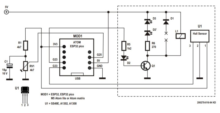
But as mentioned earlier in this article, Peter came up with the idea to add a trimmer to adjust the threshold level during run-time, as can be seen in the modified schematic diagram in Figure 3. The wiper of the preset potentiometer is connected to a second analog channel of the ESP32. This can be a temporary solution to easily tune the magnetic levitation to the correct threshold level, instead of using the push button like in the previous sketch. In this way, the third version of the software (MagLev_3.INO) can help to determine the correct threshold, which then can be hard-coded in MagLev_2.INO.
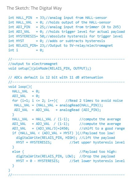
The source code is shown in the textbox. For simplicity sake, support for the M5Stack ATOM Neopixel LEDs is omitted in the sketch. If you want to keep the hardware to an absolute minimum, the additional trimmer, resistor and electrolytical capacitor (R1, RV1 and C1) could be omitted later on, with the correct threshold fixed in second version of the sketch. But the picture in Figure 4 shows that these components don’t take up much space and can effectively be hidden, though. In my opinion, this analog tuning of the digital project is a valuable addition to the levitation project. I wouldn’t remove it!
The download of the source code for the three sketches can be found at [6].
Construction
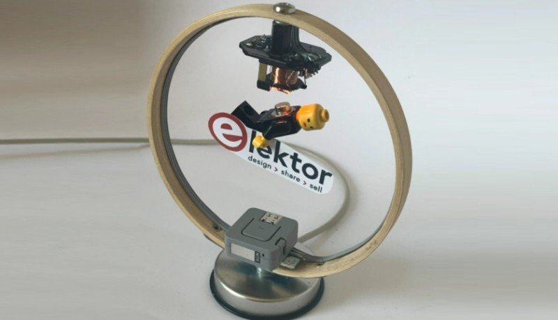
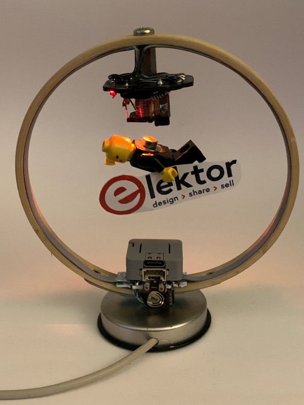
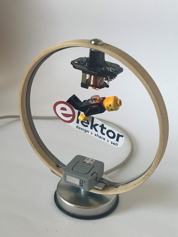
The photos in Figure 5 show how the mechanical construction of the digital levitation project can be built. The electromagnet (the modified relay board) with the Hall sensor is mounted at the top of a 10 cm diameter wooden frame, the M5Stack module at the bottom. If the trimmer option is used, the best location for the three extra components is in or at the base of the construction: it’s mechanically more stable during adjustment and it’s easier to get the components out of sight there.
Analog or Digital?
To be or not to be easy, that’s the question. We will leave it up to you to decide if you prefer the “old-school” version with the analog comparator or the more modern microcontroller solution from this second part. As mentioned earlier in this article, the 3.3 V supply voltage for the Hall sensor limits the weight of the load that can be levitated with this digital solution. The ESP32-based modules were used because of their price and small size, not because some sort of wireless connection was needed. After all, in this design, the levitated object is the only thing that doesn’t need a wire!
Discussion (1 comment)