
Modbus Over WLAN (Part 2): Software and Module Configuration
on
In the first part of this article series, we dealt with the project hardware. The module is built around a NodeMCU board fitted with an ESP8266 microcontroller, with an additional baseboard providing industry-compatible ports. After a brief introduction to the operating principle of the Modbus protocol, here we focus on how the module is controlled and the software used for this purpose. The lift door controller from the first part is again used in the example.
The Modbus Protocol
The Modbus protocol is widely used in the automotive sector. It operates according to the master/slave principle, and the bus master can control up to 246 slave devices. The bus nodes can be assigned addresses from 1 to 247. Address 0 is reserved for broadcast data; all data sent to this address is received by all nodes. The consistency of the individual data packets is ensured by CRC checksums. The slave devices have internal registers with diverse functions. Table 1 provides an overview of the Modbus functions.
| Description | Mode | Bits |
| Individual “Coil” input/output | Read/write | 1 |
| Individual “Discrete Inputs” | Read only | 1 |
| “Input Registers” (analog/digital) | Read only | 16 |
| “Holding Registers” inputs/outputs (analog/digital) | Read/write | 16 |
There are three variants of the Modbus protocol:
- Modbus RTU: Binary transmission over RS485 (EIA485).
- Modbus ASCII: Plain text transmission over RS485 (EIA485). This is less efficient than binary transmission, but human-readable. Commands can be sent using a simple terminal utility.
- Modbus TCP: In this variant the Modbus commands are transmitted using TCP/IP. This is usually over Ethernet, but with this module it is over WLAN.
For more detailed information and protocol descriptions, visit the Modbus website.
Preparing the Modbus WLAN Module
In order to use the WLAN module with the Modbus protocol, you first have to load the required firmware. For this, remove the NodeMCU board from the Modbus board and connect it to a USB port on your computer. Then open the Arduino IDE, configured as described in the first part of this article. You can download the firmware, which turns the module into a Modbus client, from the Elektor project page.
Open the downloaded file OpenPLC_ESP8266_1_0_MUX_V1_1.ino in the Arduino IDE (File -> Open). The Arduino IDE will ask whether the project should be moved to the sketchbook. Answer this with ‘Yes’. If the IDE creates a new folder, copy the header file (modbus.h) to the new folder containing the ino file, so the compiler will be able to find the header.
To enable access to the module over WLAN, the WLAN access data must be modified at the start of the source code (see Listing 1). There you should enter the access data of your own WLAN.
/*********NETWORK CONFIGURATION*********/
const char *ssid = "<YOUR_SSID>";
const char *password = "<YOUR_PASSWORD>";
/***************************************/
After making this modification, you can load the program into the Modbus module as described in the first part. The module works with DHCP, which means it will be assigned an IP address automatically by your router. You can check this in the router firmware. Alternatively, you can view the program output on the Arduino IDE serial monitor (opened by the looking glass icon at the top right). In the dropdown box at the bottom right, set the interface data rate to 115,200 baud. Listing 2 shows an example of how to output the IP address to the serial monitor. To avoid having to repeat this procedure every time you power up the Modbus module, you should assign a static IP address. All recent routers allow this option. In any case, you should note the module IP address output by the program so that you can access the module over WLAN. If you do not see any output, press the Reset button on the NodeMCU board to restart the software, since the IP address is only issued during the start-up process.
Connecting to Vodafone-3980
.......
WiFi connected
Server started
My IP: 192.168.0.85
First Test
To check whether the Modbus WLAN module is working properly, you can use the EasyModbus tool, which can be downloaded from SourceForge. EasyModbus provides a server, a client, and a library. For this test you only need the client, which can be downloaded directly. In order to use the tool, you must have a Java version installed on your PC. If Java is not yet installed, you can use the free OpenJDK, which is very popular in the developer and maker community and is a standard component of all Linux distributions. In Ubuntu, for example, you can install it with the terminal command sudo apt install openjdk-11-jdk.
To run the EasyModbus client, enter the command java -jar EasyModbusJavaClient.jar. Figure 1 shows the output of the EasyModbus client (on the left under Linux; on the right under Windows). Here you should select Modbus TCP and enter the IP address of your module. Leave the Starting Address set to 1 and change the Number of Values to 4. If you now click Read Discrete Inputs – FC 2, the four digital inputs of the module will be read and displayed. You should apply a signal to at least one of the inputs, so that you can see whether everything is working as expected.
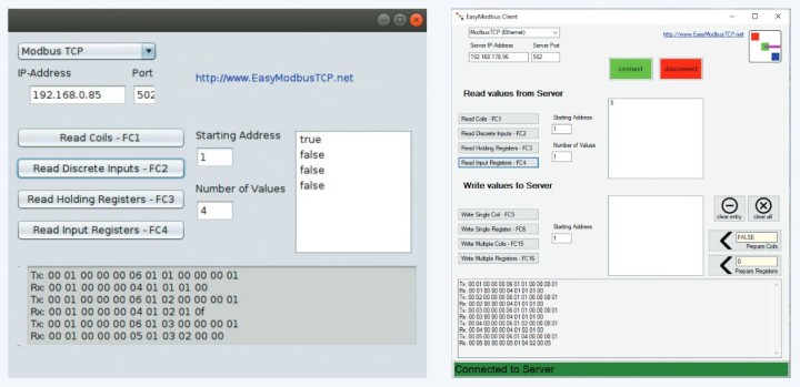
The EasyModbus client can only read data from Modbus; it cannot write data. To test writing, you can use the example program described below. The data actually transmitted can be seen at the bottom of the EasyModbus client window. This function is very helpful for debugging. If the first test was successful, you can now proceed to programming the module with Python.
Installing the Modbus +Library
To make the test more realistic, here we are using the lift door model from the first part. We wrote a program for the PC that receives the positions of the buttons and the limit switches over Modbus in order to transmit corresponding motor actions (again over Modbus).
Our Python program needs a library in order to access the Modbus. This is nothing unusual; there are Modbus libraries for virtually all programming languages. If necessary, you can even generate the bit sequences of the commands yourself and send them over the network. However, we don’t want to go into that here.
First, you should make sure that the Python package installer pip is on board, which should always be the case with fairly recent Python installations. You can check this with either $ python -m pip –version under Linux or C:\> py -m pip –version under Windows.
If the pip installer is not present, you can install it via Python with get-pip.py (don’t use the Linux package manager for this):
wget https://bootstrap.pypa.io/get-pip.py
python get-pip.py
get-pip.py
Then install the Modbus library:
$ python -m pip install -U pymodbusTCP
C:\> py -m pip install -U pymodbusTCP
You can find extensive documentation for the library, along with many code examples.
Example Program
Let’s have a detailed look at the example program in Listing 3. The first line imports the Modbus library. The next line creates a new connection object in order to communicate with a specific Modbus device. Several parameters can be passed for this. In our case we pass the IP address of the target device as host. Port 502 is the default port for Modbus TCP communication. The parameter auto_open determines whether the connection should be set up automatically or manually. In our example we chose automatic for the sake of convenience, but if you want to have complete control over connection setup, you should choose False. With manual connection setup you have more options for control and for error handling. If the parameter debug is set to True, the software will output all transmitted data to the console. This is very helpful when you are looking for a bug.
from pyModbusTCP.client import ModbusClient
client = ModbusClient(host="192.168.0.85", port=502, auto_open=True, debug=False)
while(True):
inputs=client.read_discrete_inputs(0,4)
end_switch_top = inputs[0]
end_switch_bottom = inputs[1]
push_button_down = inputs[2]
push_button_up = inputs[3]
motor_up = 0
motor_down = 1
# request end_switch
if(end_switch_top):
client.write_single_coil(motor_up,False)
print("gate open")
if(end_switch_bottom):
client.write_single_coil(motor_down,False)
print("gate closed")
# request push button
if (push_button_up and not end_switch_top):
client.write_single_coil(motor_up,True)
if (push_button_down and not end-switch_bottom):
client.write_single_coil(motor_down,True)
Using a while loop, we repeatedly run through the program as described in the first part. This means the program works cyclically, just like all industrial controllers. The code inside the loop is the main part of the program, which first reads the inputs and then converts the input values into meaningful variables. We also define variables for the two digital outputs. This makes the following program lines easier to read.
There you can see that the motor is switched off when the end points are reached. A text message is output to the console so that you can see the current door position on the computer. Last but not least, the motor is run in the respective direction when the Up or Down button is pressed. The logical AND between the limit switches prevents the relays from chattering when the door is already at an end point.
To run the program, enter the command line python tor.py. As usual, you can stop the program with Ctrl-C.
AdvancedHMI
Convenient remote control with visual feedback that you can adapt to your own purposes can be realised with a variety of PC frameworks. The program AdvancedHMI is open-source software for creating human-machine interface (HMI) applications that communicate with your PLC or other I/O devices. This software differs from other standard packages in that it allows you to create executable files instead of just configurations that are interpreted by a runtime engine. This results in very fast and efficient applications.
AdvancedHMI is based on the Microsoft .NET framework. Applications are generated in Microsoft Visual Studio Community 2019, which is available free of charge. This allows you to create basic HMIs by drag & drop without having to write any code. The .NET framework is used by a large number of developers and has a wealth of support networks. You can find much more support for AdvancedHMI than for all other standard HMI packages combined.
The author used this platform to generate a user interface to control the baseboard. It shows the status of the inputs and provides buttons that can be used to switch the outputs (Figure 2).
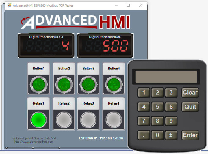
.NET programs, such as this user interface to control the baseboard, can also run under Linux with Mono. It has been tested successfully on a Raspberry Pi.
Get Control
The Modbus WLAN module makes it easy to control Modbus-compliant devices from a PC or a smartphone. This module is also a good learning project if you want to get the hang of the Modbus protocol. The hardware design, however, is so robust and error-tolerant that you can also use it in your own ESP8266 projects if you want to control and read industrial devices such as solenoid valves, motors, and other kinds of sensors or actuators.
Comments About Modbus?
Do you have any technical questions or comments about Modbus or this article series? If so, please contact the author at josef@bernhardt.de or the editorial staff at editor@elektor.com.
About the Authors
Josef Bernhardt developed an interest in electronics at an early age. He built his first crystal radio at the age of twelve, and carried on with other circuits. He started acquiring experience with programming in the 1980s with the Commodore VC20, and he also knows his way around assembly language programming on the 8088. He can look back on more than 30 years of electronics evolution at the University of Regensburg, where he worked in the field of electronic and software development. Using his own SMD production facility, he also implements electronic projects for customers.
Martin Mohr saw the light of day in the era of magnetic core memories and Strowger switches, enabling him to personally experience the entire evolution of modern computer technology. His fascination with everything that blinks dates back to his early youth and was further reinforced by his electronics training. After completing a course of study in informatics, he worked primarily on the development of Java applications, but the Raspberry Pi has rekindled his passion for electronics.
Discussion (1 comment)