
Too Quick to Code and Too Slow to Test?
on
The Dangers of Woodpeckers
It was one of those moments that, quite literally, generated an ‘aha moment’ in my head. Researching background material for the development of a training course, I wondered why embedded software developers seemed so reluctant to use concepts and methodologies that were becoming commonplace in other branches of software development. I had regularly encountered engineers who had not introduced coding standards, despite multiple people working on the development of software for a microcontroller-based project. None of them had defined any development design rules that would allow for portable, reusable code. And object-oriented design, modeling, and simulation weren’t on the radar. It was at this point that this, seemingly pertinent, quote appeared:
“If carpenters made buildings the way programmers make programs, the first woodpecker to come along would destroy all of civilization.”
This slightly modified version of Weinberg’s Law really struck a chord. Why weren’t embedded software developers drawing upon computer science research and building their code with an appropriate architecture or using modeling and simulation?
Too Quick to Code?
One answer is that it could be a result of the generation of the engineers concerned. Having grown-up with resource-limited, 8-bit microcontrollers and mastered how to squeeze every ounce of performance out of them in assembler, abstraction and the thought of tool-generated code implied code bloat and an inevitable loss of control. Even the move to C had been a challenge for some, despite its closeness to the underlying hardware.
Another aspect is how C is typically taught, focusing on the ‘grammar’ rather than how best to use it. However, just like a spoken language, competence in grammar does not make the student an eloquent orator.
Until the emergence of Internet of Things (IoT) applications, a microcontroller’s firmware could not be updated without an expensive jaunt into the field where the equipment was installed. Despite this inherent lack of room for error, the established approach to code development by some embedded software developers remained unchanged.
Is There ROOM for a New(er) Development Approach?
While the code executing on microcontrollers past could often be implemented using a simple state machine, the challenges being tackled today are genuinely multi-dimensional. Today it is not unusual for a microcontroller to commutate an electrical motor using field-oriented control (FOC) as well as hosting a number of other tasks. Just determining the rotor angle and, from this, the next commutation point in real-time is a significant undertaking, even if the required software is already available.
When this is built into a household washing machine, IEC 60730 (Automatic electrical controls — Part 1: General requirements) also needs to be considered. Most microcontroller vendors will offer a ‘Class B’ library that executes a variety of tests, covering CPU registers, program counter and memory integrity, as well as testing the clock. This code needs to be executed ‘in parallel’ to real-time motor control. Additionally, there are likely to be communication interfaces in use that must also respond in a timely manner, along with a human-machine interface. While an embedded software developer can be sure all these features operate in isolation, what will happen when they are all integrated?
One option is to use the Unified Modeling Language (UML) and simulate a model of the application. But here, there is often significant push-back from embedded software developers. One of the primary concerns is that it is a waste of time. After all, if you’re going to go to the trouble of building a model of the application, you may as well be coding it. Also, UML has been given a bad name due to misuse as people have attempted to apply it to every part of a system. This abstracted way of working also requires a different development methodology, and trying to convince a team of developers to adopt new methods is challenging.
This concern regarding coding everything twice, once as a model and then again as the application code, is known as a phase discontinuity. Ideally, any modeling approach should resolve this which is the case with the Real-Time Object-Oriented Modeling (ROOM) domain specific language (DSL) [6]. Designed specifically for the needs of those developing event-driven, real-time systems, it supports modeling and simulation while also being capable of generating code that can be used on the target hardware.
It describes software systems along the three-dimensions of structure, behavior, and inheritance. Structures can be represented by diagrams containing actors that communicate with each other via ports. Messages passing between them are handled by runtime libraries that provide the services required to support this. The behavior of actors are described using hierarchical finite-state machines that can also be generated as diagrams. Entry and exit code can be defined for the states in the target language of the code generator being used (C compiler for a microcontroller). State transitions occur upon receipt of messages via ports, and any resultant response returns through the ports.
Inheritance provides the object-oriented aspect of ROOM, treating actors as classes that can be instantiated multiple times. Each instantiation also inherits the state machine that, naturally, can be extended if required. Finally, a further concept is that of layering. For example, this allows communication between applications or access to services such as timers through service access points (SAP).
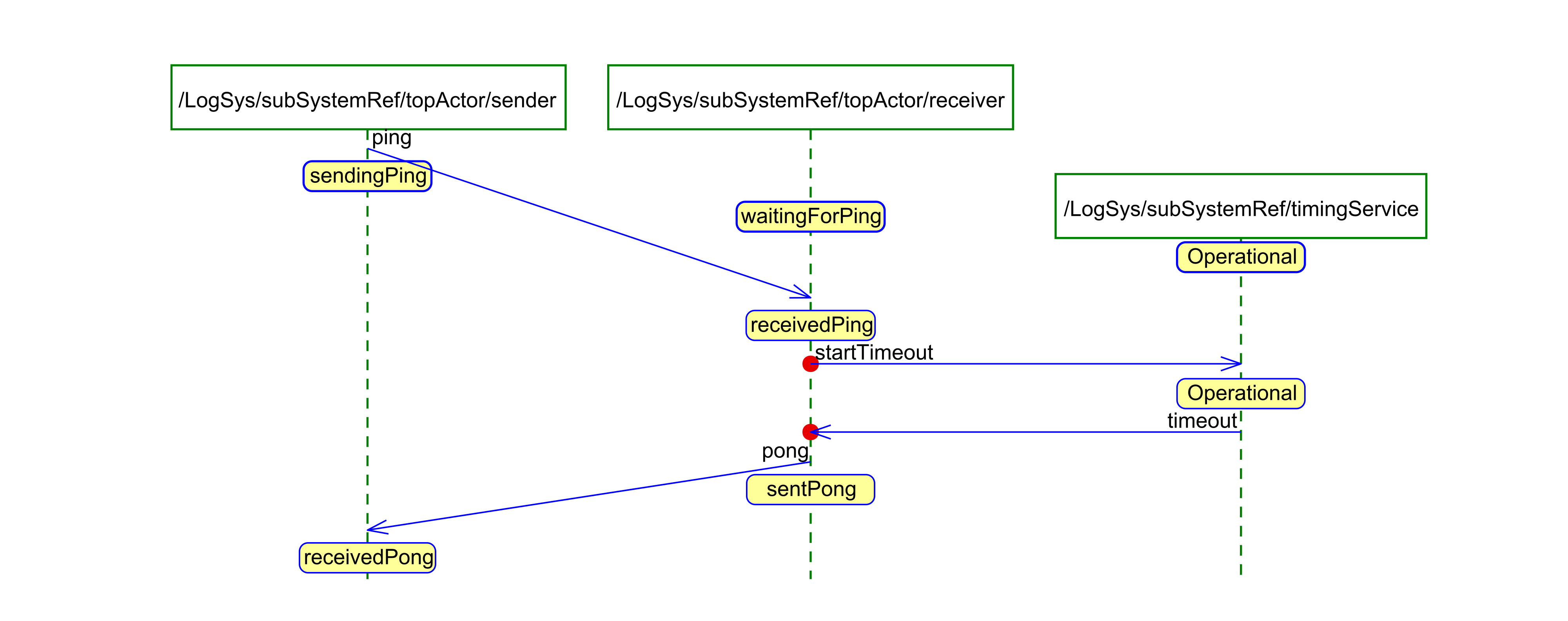
This software development approach is supported by eTrice, a package that can be added to the Eclipse IDE. Models can be created graphically or textually that generate code in C, C++, or Java. Simulation of the model generates message sequence charts (MSC) for visualization in the external tool Trace2UML, part of Astade, a UML tool. A tutorial project shows how a simple ping-pong application can be implemented (Figure 1), with the delay in the response provided by a timer SAP.
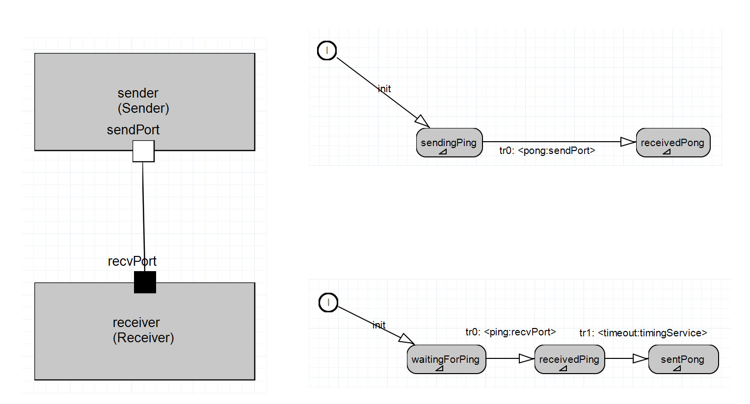
The structure and behavior can be examined graphically or in the ROOM DSL. Executing the model provides the results on a command line. Finally, the result of the simulation can be examined as an MSC (Figure 2).
Why So Slow to Test?
After rushing to start coding, many embedded development teams seem to be very reluctant to begin testing until a good portion of application development is complete. The reasons for this are diverse and complex. They start with the misguided view that testing is expensive and has to be done by a testing team or department. Lack of clear, testable requirements for individual software modules is also an issue. And, perhaps, the availability of powerful debuggers for our chosen development IDE gives us the feeling that we checked everything as we wrote the code.
The results of coding mistakes are humorously discussed in Lisa Simone’s book “If I Only Changed the Software, Why is the Phone on Fire?” In one example, an error in a temperature control algorithm is the result of an inappropriately chosen data type. While Simone excellently describes the debugging process to find such issues, they should have been detected through unit testing.
Unit testing is a white-box style test, meaning the test is written with a knowledge of the source code, typically by the person who developed it. On a microcontroller, this requires writing an application that can execute the code, evaluate the responses, and then output the results, most likely over a serial interface to a console. This means that a hardware platform would be required on which to execute the tests. An Arduino, and many of its clones, that include a UART to USB converter make this much easier by allowing test results to be output to a console. But it is still a significant amount of work to maintain a testing application for each software module developed.
The software testIDEA from iSYSTEM provides an excellent and straightforward way of lowering the testing effort. As a debug tool manufacturer, their development environment already has access to the source code and the microcontroller's internal workings via the debugging interface. All it requires is a compiled application (ELF format) that can be programmed into the microcontroller’s flash memory.
Tests are defined in testIDEA that execute individual functions using defined test values for the function parameters (Figure 3).
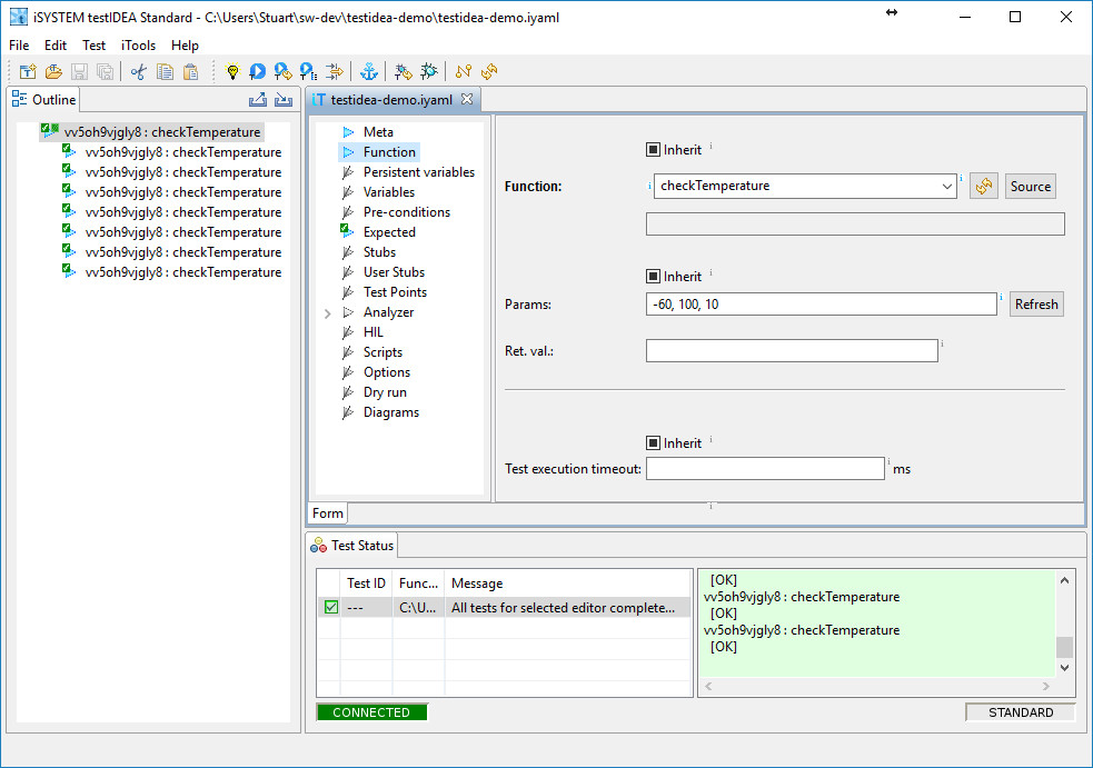
With full access to the RAM, all data types and pointers can be inserted with ease. Success or failure of the test depends on the return value provided by the function called. Additionally, tracing can also be enabled during testing, providing code coverage in addition to the results of the testing. C++ is also supported but requires the additional step of calling the constructor before any of the methods can be tested. Tests can also be exported into Python, allowing test execution to be automated.
One impressive capability is that all the internal and private variables can be injected with values or evaluated as part of the testing procedure. When you’re the debugger, you can do anything. This is helpful when testing code compiled using optimization. As is well known, due to the removal of unused code and shuffling of code fragments, software built using optimizations often results in code that doesn’t function precisely as the non-optimized code did. Debugging such code is especially challenging since much of the relationship between the source binary code is lost. By running the same suite of testIDEA tests it is possible to determine if the basic code still functions as expected before moving to testing at the integration or system level.
How Many Tests Are Enough?
For those new to testing, it can be challenging to determine the optimal strategy to apply. Testing quickly becomes much like the rabbit hole of Alice in Wonderland in that the more you look at what to test, the more there seems to test. Again, due to the multi-dimensional aspects and dependencies, it becomes unclear how much testing is enough. Anyone who has worked on a safety-critical project will also know that the applicable standards, such as ISO 26262 for automotive and ISO 14971 and IEC 60601 for medical, are open to interpretation. As an example, ISO 26262 states branch coverage as “highly recommended” for structural coverage metrics, while statement coverage and MC/DC (modified condition/decision coverage) is only “recommended”. Only by working with experts in testing can you determine what this means in the context of your application and how best to implement it.
To ensure that all possible branches of code are covered and that, as far as possible, all permutations of code have been tested, help is at hand in the form of MBTsuite from sepp.med GmbH. This model-based testing framework is ideally suited to integration and system testing as, at this stage of the development process, it is difficult to determine all possible test permutations.
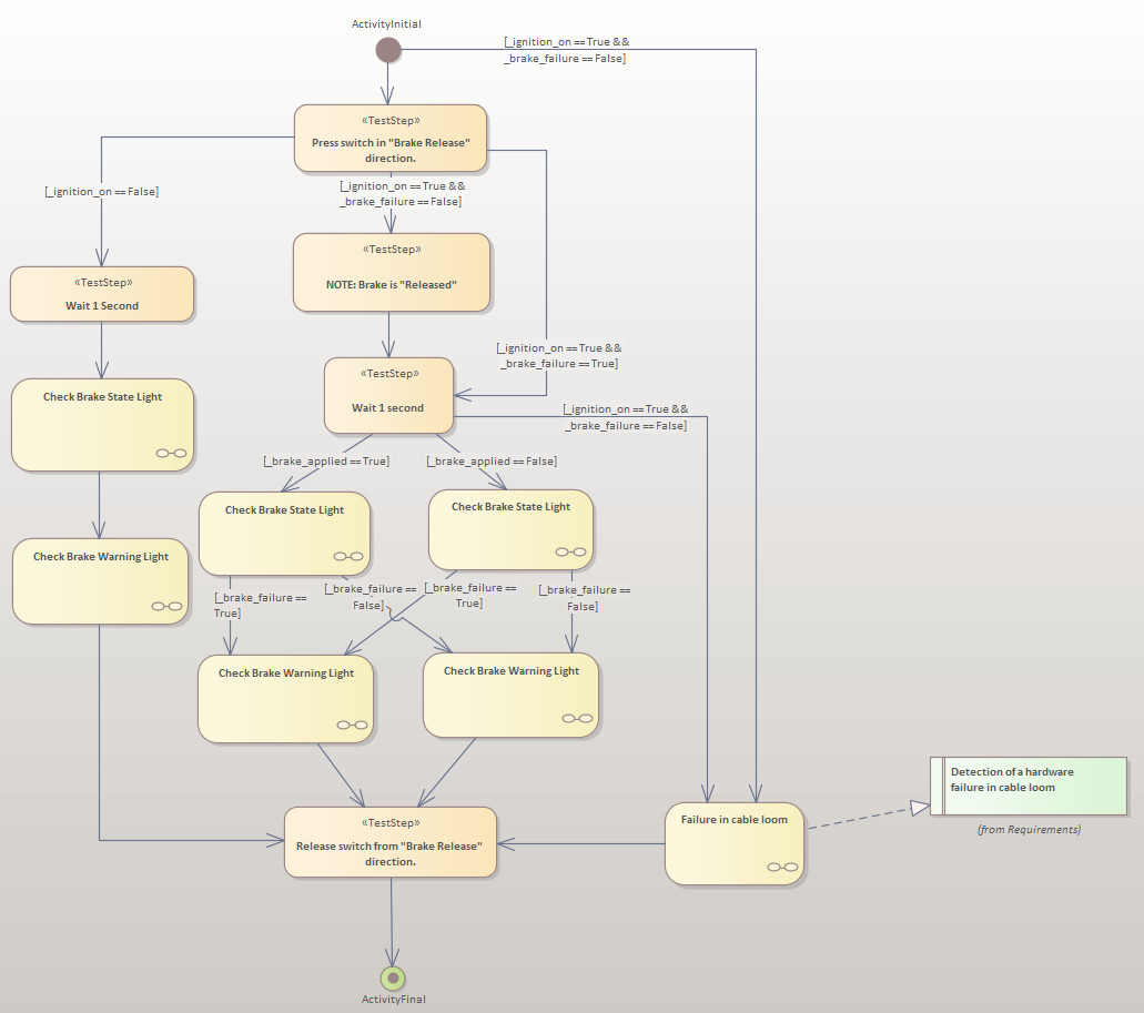
The process starts by examining the system's requirements and entering them into a tool such as Enterprise Architect. From here, a model of the system can be constructed, with the model being linked back to related requirements to show how they are tested. Complex aspects of the design can be broken down into sub-models, keeping the top-level clean and the model well abstracted (Figure 4, 5).
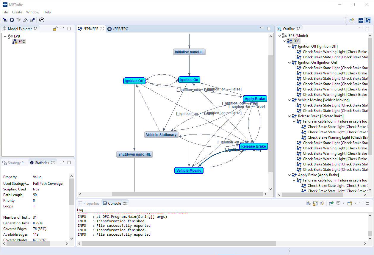
With the model complete, it is imported into MBTsuite. The tool allows a test plan to be generated according to a variety of strategies. Full Path Coverage would attempt to develop a testing plan covering the entirety of the model, while Shortest Path attempts to find the shortest paths through the model, as the name suggests (Figure 6).
The Random strategy can help discover issues that may not be found using the more formal approaches. It is also ideal for performing a smoke test to ensure both the hardware-under-test and the test harness are working correctly.
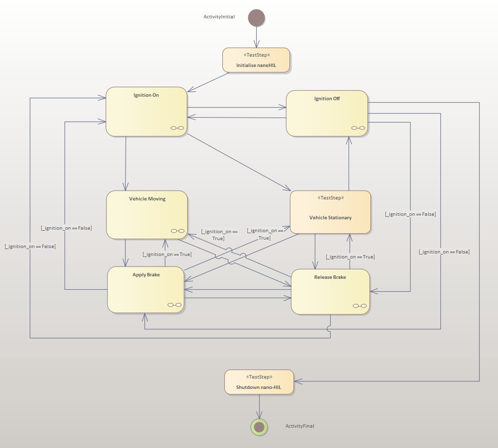
As can be seen in the Electric Park Brake (EPB) model (Figure 4), it is possible to move cyclically through many sections of the model, potentially resulting in an endless loop. To limit such recursive loops, each testing strategy can be limited in scope with parameters such as number of loop runs and maximum path length. Sections of the model can also be named, allowing tests for a particular feature or capability to be generated.
At its simplest, MBTsuite generates the tests as a Word or Excel document that lists test steps and verification points where an expected outcome of each is given. Manual testing can then provide a pass/fail result using a tick-box for each step. However, if an automated approach to testing is desired, the test can be exported in an appropriate format, such as Python, in combination with a suitable template.
Rapidly Testing on Hardware
Ideally, hardware-in-the-loop (HIL) testing is required to put an application through its paces. This is especially helpful for applications operating at dangerous voltages and currents or when moving mechanical parts are in play. However, such a test harness can be very expensive. Many teams may also only have one harness available to test multiple variants of the products they develop. As a result, the HIL can become a severe bottle-neck and testing therefore occurs very late in the development process. Under the current restrictions imposed by the Coronavirus, HIL testing may simply be unavailable.
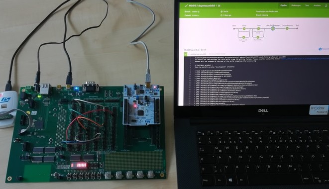
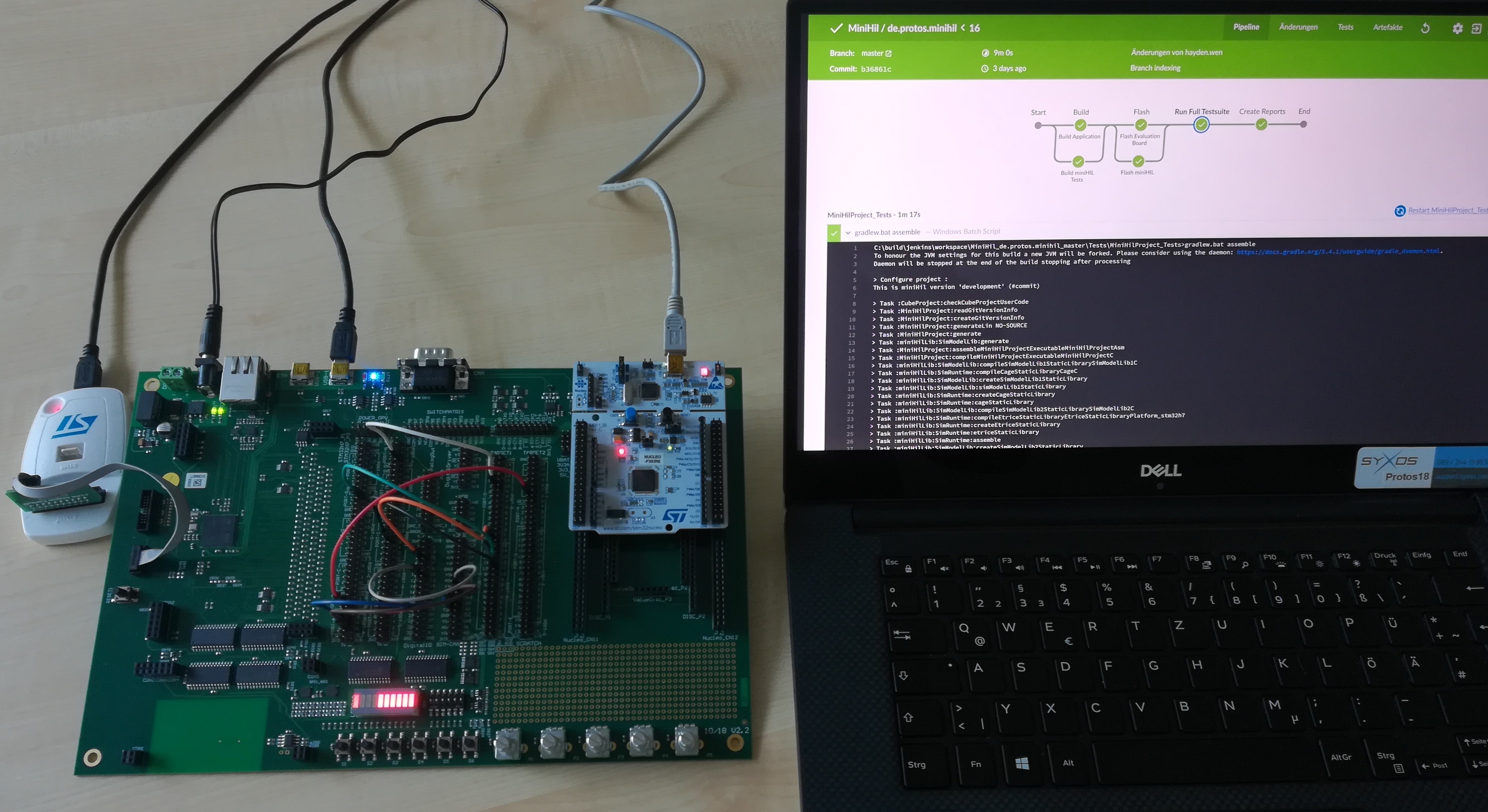
To circumvent this challenge, PROTOS Software GmbH has developed its miniHIL platform. It consists of a hardware board around the size of an A4 piece of paper. On the right-hand side is space for an STM32 Nucleo development board, while on the left-hand side sits a powerful STM32H743. In the middle are a collection of pins that serve as a connection matrix between the two sides. The STM32H743 serves to simulate the plant that the STM32 Nucleo controls and provide any signals the plant generates. This makes it ideal for testing motor control application code without having to run the code on a real washing machine or electric drill.
The environment is supported by eTrice and the CaGe (Case Generator) language to develop the tests. Not only does this allow the developer to rapidly check that code changes function as expected, but the entire platform can be combined with a continuous integration (CI) platform such as Jenkins. Automated tests can thus be executed regularly on the hardware, perhaps overnight, delivering the results on a dashboard that can be reviewed first-thing the next day (Figure 7).
Finding Those Sporadic Failures
Today’s automotive applications are exceptionally complex, with the amount of code in a vehicle purported to be similar to that used to code Windows NT [16]. With the distributed nature of code development, involving many suppliers and even the automotive customer themselves in some cases, it is not functionality but timing that is increasingly the cause of sporadic, hard-to-find failures. This is compounded by the use of multicore processors and even virtual machines.
Despite the wealth of testing undertaken, strange things still happen once the hardware is ready to ship or, worse, once it is already in the field. One example comes from the field of automotive, where two electronic control units (ECU) connected via a CAN bus displayed intermittent failures. ECU A connected to ECU B showed failures, but not when connected to ECU C. ECU B and ECU C worked fine together. The issue was linked to slight differences in quartz frequency in each ECU. Over time, the microcontroller’s timing diverged enough to result in a CAN message occasionally being lost.
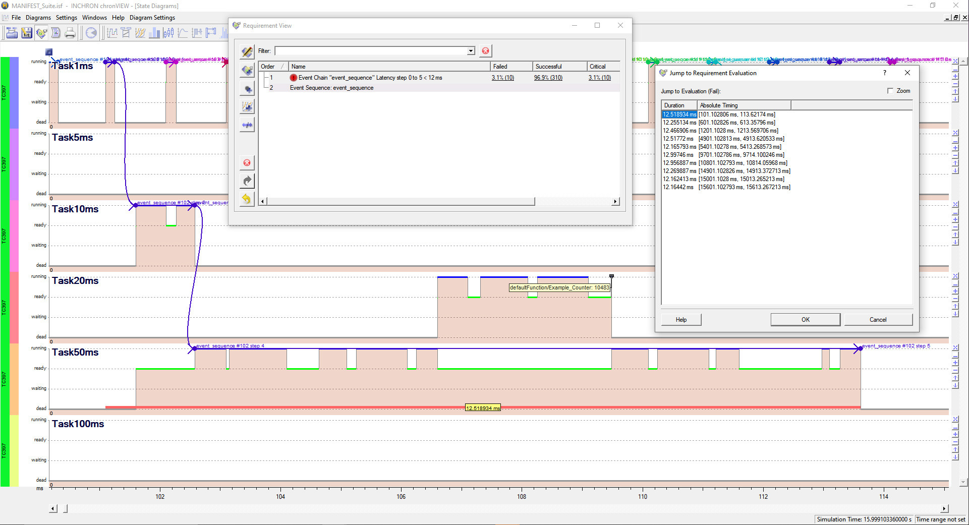
Tools such as chronSIM and chronVIEW from Inchron AG and the TA Tool Suite from Vector Informatik GmbH give timing the same status as functionality. They allow models to be built of the target system before any code is written, enabling system architects to determine the optimal architecture for the code on a variety of target hardware. The impact of assigning code to differing cores can also be assessed, essential when heterogeneous multicore processors operating at differing frequencies are used. Finally, the evaluation of chains of events (Figure 8), the timing from the sensor through the system to the actuator, can be undertaken.
This is even more critical in today’s era of autonomous driving capability, where sensor fusion combines inputs from multiple sensors delivering data at differing rates.
By focusing on both timing and functionality, and defining the allowed execution time of sections of code, the time-related issue seen in the CAN-connected ECUs mentioned can be avoided by design. Models can also be simulated to understand the impact of clock frequency variations, core assignment, code execution time, or changes in clock frequency. To ensure that the timing requirements are fulfilled, these tools can also analyze the trace data captured from the microcontroller operating on real hardware, checking that the execution time of code sections under differing test conditions still meets the requirements.
Time to Take Modeling More Seriously?
Embedded software development has remained very traditional. The ‘rush-to-code’ mindset is exacerbated by the wide range of development toolchains provided by microcontroller suppliers that focus on coding and debugging on target. Being mainly without cost, they diminish the value of alternative toolchains whose existence depends on paid licensing models.
Tools that support modeling and simulation of embedded systems provide a way of taking a step back and abstracting before getting into the hard work of coding. Due to the inherent repetitive testing and analysis that results from this approach, architectural issues can be determined before application development reaches a stage where it becomes too expensive to change course. Bench-top HIL with simulation solutions allow even small code changes to be assessed in compact time cycles, rather than waiting for a big test of fully integrated code. Finally, the most complex real-time applications, such as those being developed for automotive, where modeling and testing are already in widespread use, need to look beyond functional requirements and include timing requirements.
Perhaps the biggest challenge to adopting these model-based tools is the fear of change. Their abstracted nature pushes traditional embedded developers into a realm of the unknown, far away from the hardware they know and love. They require changes to development processes, which leads to a lot of push-back. Until they are actually in place, their benefits, although clear and sensible on paper, remain intangible. However, many of the tools discussed here have been around for more than a decade, indicating that they have established their place and role. It remains for individual developers to investigate each option’s appropriateness in the context of their processes and the products they develop since savings in development time and costs, and improvements in quality are there to be had.
Want More on Code and Sofware Development?
Take out an Elektor membership today and never miss an article, project, or tutorial.
Discussion (0 comments)