
Circular Christmas Tree 2023 [230508]
3D Circular Christmas Tree with 36 digital 8 mm RGB LEDs WS2812D-F8 controlled externally or by an onboard Arduino Nano (ESP32)
Published in Elektor Magazine.
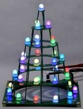
This Christmas Tree is all about the shape of the construction and the use of 8 mm digital RGB LEDs. Its appearance is more like a real tree than most of the flat PCBs with a pine tree styled outline. Instead of a 2D design this is a 3D design. It’s based on two earlier versions: https://www.elektormagazine.com/labs/130478-xmas-tree-2014 and https://www.elektormagazine.com/labs/circular-christmas-tree-150453. The first one used a simple random generator with 2 standard logic ICs and small white SMD LEDs. The latter a microcontroller with the LEDs connected in a matrix of 6 x 6. This new version uses 8 mm digital RGB through hole LEDs of type WS2812D-F8. This makes the circuit very simple. Instead of a matrix the in and outputs of the digital LEDs are connected in series, with each LED connected to a 5V power supply. The chain of LEDs can be addresses like a NeoPixel LED strip. There is an abondance of software in many programming languages available on the web showing how to do this. Connector K1 is connected to the internal +5 V (4.3 V), ground and the input of the first LED (through jumper JP1). This way a variety of external microprocessors, microcontrollers or modules can be used to control the LEDs of the Circular Christmas Tree. To make the tree independent of an external circuit an Arduino Nano ESP32 module can mounted on the base PCB.
To connect the PCBs 39 pieces of wire connect the +5 V and ground from a PCB to the one above it. One extra wire connects each Dout of the LED on a lower PCB to first LED on the PCB above it. In the schematic these are connections PA1-PA2 through PE5-PE6.
If an onboard Arduino Nano ESP32 is used to control the LEDs DIP-switch S1 and the small trimmer P1 can be mounted on the PCB as well. Software can use these components to select different patterns or adjust brightness. Without the onboard module these components serve no purpose.
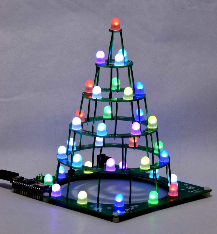
The next photos of the Circular Christmas Tree don’t really show the full bright color of the LEDs but still give a good impression.
The program is an example how to make different patterns, selected with dipswitch S1. Trimmer P1 is used to set the brightness of the LEDs, from 0 to maximal.
In main.py the following modes can be selected
(Mode 0 is all dipswitches set to 0. Mode 7 is S1-1, S1-2 and S1-3 set to 1, S1-4 set to 0)
Mode S1:
0: all 36 LEDs the same color, first red, next green-blue-yellow-magenta-cyan-white, then red
again and so on
1: all LEDs red
2: all LEDs green
3: all LEDs blue
4: all LEDs yellow
5: all LEDs magenta
6: all LEDs cyan
7: all LEDs white
8: colors red-green-blue-yellow-magenta-cyan-white shift continuously in sequence through all the LEDs
9: all LEDs get the same color, next color is random
10: all LEDs change color, the colors are random
So there’s still room for 4 extra modes. How about all LEDs on one PCB get the same color, but each PCB a different color? And many more patterns are possible. If you’re looking for a fun MicroPython project using a ESP32 this may be the one for you. But also software from other projects that use a ESP32 can be incorporated in the software or transferred to this Circular Christmas Tree. Look for instance at the software of project 160112 Wearable Wi-Fi Gadget (https://www.elektormagazine.com/articles/wearable-wifi-gadget). In Home Assistant a number of color effects are standard incorporated, some with a funny twinkle effect. You could set up a whole forest you can turn on or off and change effects and add whatever you can think of.
https://github.com/arduino/lab-micropython-editor/releases/download/0.8.0/Arduino.Lab.for.Micropython-win_x64.zip
Arduino MicroPython Installer
https://github.com/arduino/lab-micropython-installer/releases/tag/v1.2.1
MicroPython course MicroPython 101 by Arduino
https://docs.arduino.cc/micropython-course/
Documentation about the Arduino Nano ESP32
https://docs.arduino.cc/hardware/nano-esp32
Arduino Nano ESP32 with headers
https://www.elektor.com/arduino-nano-esp32-with-headers
R1-R36 = 75 Ω, 0W125, 5 %, SMD 0805
P1 = 10 kΩ, 0W1, 20 %, trimmer, top adjust, 6 mm round (Piher PT6KV-103A2020)
Capacitor
C1-C36 = 100 n, 50 V, 5 %, X7R, SMD 0805
C37, C38 = 47u, 6V3, 10 %, tantalum, Case Size A (1206)
Semiconductor
D1, D2 = S5J-E3/57T, SMD Case Size SMC
LED1-LED36 = WS2812D-F8, 8 mm, THT
MOD1 (optional) = Arduino Nano ESP32 with headers
Other
K1, JP1 = Pin header, 3x1, vertical, pitch 2.54 mm
JP1 = shunt jumper, 2.54 mm spacing
K2 = MJ-179PH (Multicomp Pro), DC Power Connector, 4 A, Pin Diam. 1.95 mm
S1 = DIP switch, 4way
PA1-PE6 = 2 m wire, 0.81 mm solid, 0.52 mm2 / 20AWG, insulated green (Alpha Wire 3053/1 GR005)
H1-H5 = Nylon standoff, female-female, M3, 5 mm
H1-H5 = Nylon screw, M3, 5 mm
Misc.
PCB 230508-1
The PCB of the Circular Christmas Tree is a panel and the 5 circular PCBs must be removed from the base PCB by breaking the connections between the individual PCBs.
After separating the PCB's the SMD components can be soldered. Figure 9 shows all SMD components soldered and the PCBs positioned as they must be connected.
The distance between the leads of the WS2812D-F8 LEDs is very small. To make soldering the LEDs easier the holes are just big enough, more copper for 4 the pads, for the thin part of the leads to fit through. To mount the body of the LEDs against the PCBs the leads of all the LEDs have to be cut before soldering, as figure 10 shows.
In total 39 pieces of wire connect the PCBs. Cut all wires to a length of 4 cm and strip 5 mm of the insulation at both ends. The 3 cm insulation left of all 39 pieces of wire should be as equal as possible. The length of the insulation ensure the PCBs are mounted perfectly parallel to each other.
Figures 13 through 16 show the overlay and copper on top and bottom of PCB 230508-1 v1.1.
This Christmas Tree is all about the shape of the construction and the use of 8 mm digital RGB LEDs. Its appearance is more like a real tree than most of the flat PCBs with a pine tree styled outline. Instead of a 2D design this is a 3D design. It’s based on two earlier versions: https://www.elektormagazine.com/labs/130478-xmas-tree-2014 and https://www.elektormagazine.com/labs/circular-christmas-tree-150453. The first one used a simple random generator with 2 standard logic ICs and small white SMD LEDs. The latter a microcontroller with the LEDs connected in a matrix of 6 x 6. This new version uses 8 mm digital RGB through hole LEDs of type WS2812D-F8. This makes the circuit very simple. Instead of a matrix the in and outputs of the digital LEDs are connected in series, with each LED connected to a 5V power supply. The chain of LEDs can be addresses like a NeoPixel LED strip. There is an abondance of software in many programming languages available on the web showing how to do this. Connector K1 is connected to the internal +5 V (4.3 V), ground and the input of the first LED (through jumper JP1). This way a variety of external microprocessors, microcontrollers or modules can be used to control the LEDs of the Circular Christmas Tree. To make the tree independent of an external circuit an Arduino Nano ESP32 module can mounted on the base PCB.
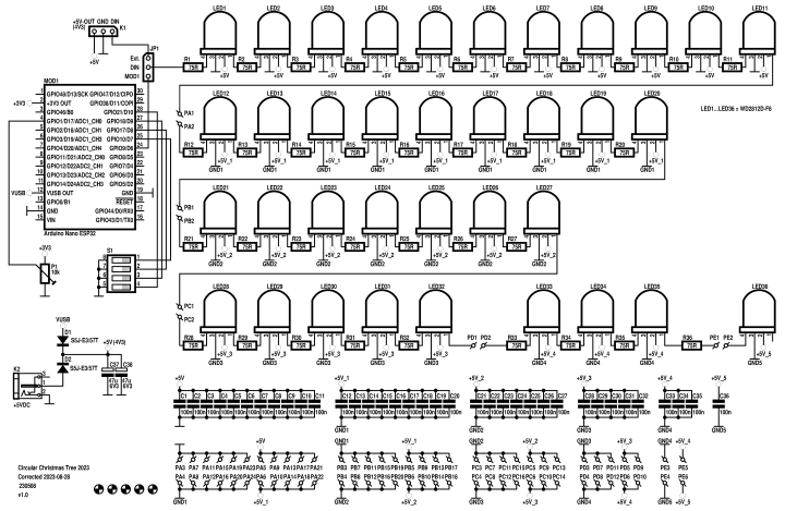
Schematic
Figure 1. Schematic of the Circular Christmas Tree.
The circuit consists essentially of 36 digital RGB LEDs of type WS2812D-F8 with their inputs (Din) and outputs (Dout) connected in series and each powered by a 5 V power supply. The actual voltage on the LEDs is lower because of diodes D1 and D2, used for protection. The first LED can be controlled by an external microprocessor, microcontroller or module or optional onboard module Arduino Nano ESP32 (MOD1). Jumper JP1 selects the control signal of LED1. The use of an Arduino Nano ESP32 makes the tree more versatile. Through software it is possible to change lighting patterns of the tree remotely by using the onboard Wi-Fi and/or Bluetooth LE. All inputs of the LEDs have a 75 Ω resistor in series (R1…R36, according to the datasheet of the WS2812D-F8). Each LED is decoupled by a 100 nF capacitor (C1…C36). The power supply for the LEDs on the base PCB is additionally decoupled by 47 µF tantalum capacitors C37 and C38. All these components are SMDs and mounted on the bottom of the PCBs so they’re kept out of sight. The LEDs can be powered by a 5 VDC AC adapter, preferably rated at least 1.5 A, through DC power connector K2 or by VBUS of MOD1 (when mounted). Diodes D1 and D2 (5 A, 50 VDC, S5J-E3/57T, SMD Case Size SMC), also mounted on the bottom side of the PCB, prevent the two power supplies are connected directly. It’s possible to connect a power supply to both, MOD1 and K2, but is not necessary. The module itself is powered by its USB-C connector and the maximum current of the VBUS pin of the module is sufficient (assuming the AC adapter connector to it is). The diodes are intentionally no Schottky types. Voltage drop across the diodes is higher and making sure 3.3 V logic signals are well within specification of the WS2812D-F8. For this reason, if LED1 is controlled by an external circuit, it’s best to use the power supply voltage of K1 to power this external circuit. The actual voltage on K1 will be lower than the 5 V of K2, around 4.3 V or even lower at high current/brightness setting, because of the voltage drop across D2.To connect the PCBs 39 pieces of wire connect the +5 V and ground from a PCB to the one above it. One extra wire connects each Dout of the LED on a lower PCB to first LED on the PCB above it. In the schematic these are connections PA1-PA2 through PE5-PE6.
If an onboard Arduino Nano ESP32 is used to control the LEDs DIP-switch S1 and the small trimmer P1 can be mounted on the PCB as well. Software can use these components to select different patterns or adjust brightness. Without the onboard module these components serve no purpose.
Power Supply
Power supply for the LEDs is a +5 V AC adapter with a barrel connector, connected to K2. The kit available in our shop only contains the parts for the PCB including the small trimmer and DIP-switch. The Arduino Nano ESP32 module and an AC adapter are not included. The onboard use of an Arduino Nano ESP32 module is optional and must be purchased separately. This module has a USB-C connector which also powers the LEDs through its VBUS pin. Two diodes (D1, D2) prevent the two power supplies being connected directly to each other. VBUS of the module is internally connected to the 5V of the USB-C connector through a Schottky diode of type PMEG6020AELR (Nexperia). This diode is rated 2 A. At this moment the maximum current of the VBUS pin of the Arduino Nano is not specified in its datasheet (Arduino_Nano_ESP32_ABX00083-datasheet.pdf). The current of the WS2812D-F8 is 12 mA according to a family overview on the manufacturers web site. However the datasheet has 15 mA in its name (WS2812D-F8-15mA_V1.1_EN.pdf) and many parameters are specified at the condition of IF = 20 mA. In our prototype the maximum current at maximum setting (3 x 255 decimal per LED) was just under 11 mA per color, far from 20 mA. These different specifications are very confusing. Apparently the 12 mA is the correct value. Assuming 12 mA is the correct value maximum current of the LEDs at maximum brightness setting would be 36 (LEDs) x 3 (colors) x 12 mA = 1.3 A. In our prototype of the Christmas Tree total maximum current measured is 1.156 mA. The VBUS pin of MOD1 shouldn’t have a problem with this current. But, in general we strongly advise never to use the maximum current of a LED, it shortens its lifespan/brightness much faster! But also, the brightness between for instance a third and its maximum rated current is not that much lower. Consider taking this into account when writing the software. Setting the LEDs to give white light in a well lit room and the LEDs lighting brightly (all LEDs set to white) 200 mA total current of the LEDs is enough. If you keep the maximum setting at let’s say 500 mA the maximum power of the AC adapter for K2 can be much lower.PCB
The 136 x 136 mm PCB is a panel with the base PCB holding the 5 circular shaped PCBs with 24 breakoff-bridges. It takes some force to break them. The construction manual gives all details how to build this Circular Christmas Tree. The copper of the 39 pieces of wire to connect the PCBs is 0.8 mm thick. These wires also shape the tree and is the reason we chose green insulated wire. But, if you think a bare tin-plated wire is better looking you can of course strip all insulation. Closely observe all PCBs are mounted parallel with a distance of 3 cm to each next upper one. The large number of wires make the construction quite rigid. To keep voltage drop from bottom to the top minimal all wires, except the signal wire, are connected to +5 V and ground alternately. Wenn stripping all insulation beware of a possible short circuit between the bare wires! The tracks for the power supply are 1 mm wide. All SMD components are mounted on the bottom side of the PCBs. Separate the PCBs before soldering. No other components are on top of the circular shaped PCBs except for the LEDs. Through hole components JP1, K1, K2, P1, S1 and MOD1 are placed on top of the square base PCB. Since SMD components are used in this project some experience with soldering these small components is recommended. Using a soldering iron with a fine tip and thin solder the 0805 resistors and capacitors are not that difficult to solder. Recommended is to use very thin solder, 0.35 mm thick ,ensuring not too much solder will be used for the solder joints. The tree is placed on 5 white nylon 5 mm high standoffs and fastened with 5 white nylon screws. These are less noticeable. Optional module MOD1 is placed in a corner of the PCB to keep the base as small as possible. P1 and S1 are placed next to the module.
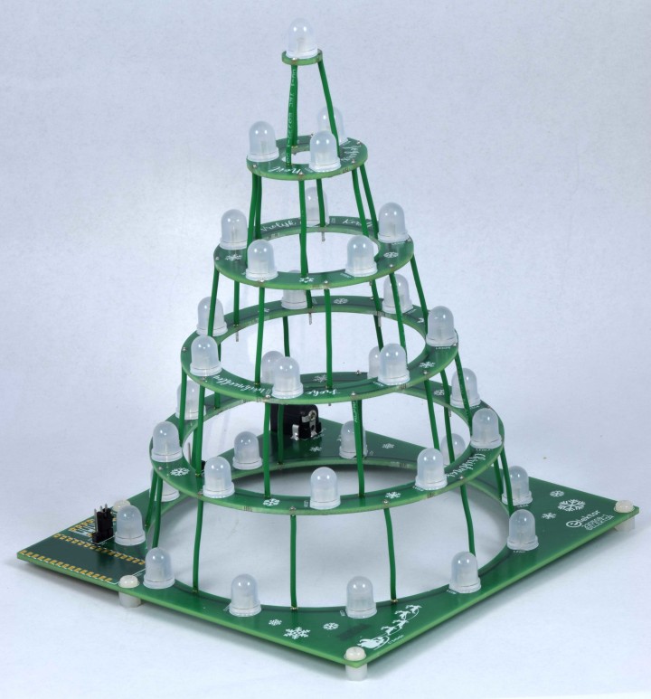
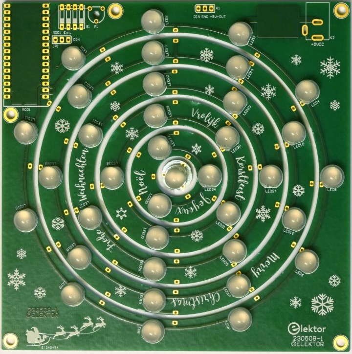
Figure 2. The finished construction of the Circular Christmas Tree (PCB 230508-1 v1.0).
Figure 3. Test setup with external Arduino Nano ESP32 (PCB 230508-1 v1.0).
Optional Module Arduino Nano ESP32
To make this Christmas Tree work independent of any external circuit an Arduino Nano ESP32 (or other Nano compatible board) module (MOD1) can be placed on the base PCB along with small trimmer P1 and DIP-switch S1. Set jumper JP1 to position MOD1. The two extra components can be used to adjust and/or select brightness/speed and different patterns/modes. Programming the module is up to the user and can be done with the latest version the Arduino IDE and the C programming language. Or, if you are looking for a MicroPython project this Christmas Tree is also a good choice. A dedicated IDE for MicroPython called Arduino Lab for MicroPython can be downloaded from github. Also necessary is a MicroPython Installer then, also available from github. It’s all well documented on the website of Arduino and also gives beginners good resources to get it working. An AC adapter with a UCB-C connecter is needed now to power the tree once the development of the software is finished. When working on the software connecting the module to a USB-C port of a desktop computer or laptop shouldn’t be a problem. The maximum current available depends of course on the specific port. Through a USB-C – USB-A adapters or adapter cable the Arduino Nano can also be connected to an “old” USB-A port when the brightness is kept low. Current is limited to 500 mA then, something to keep in mind when testing the software! Or also connect a power supply to K2 and set the voltage a little higher than 5V so it will power the LEDs.
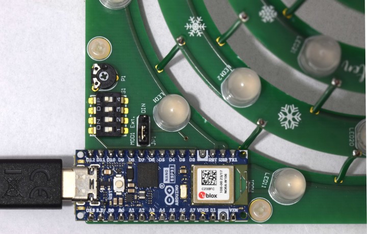
Figure 4. Detail of MOD1, S1 and P1 mounted on the base PCB.
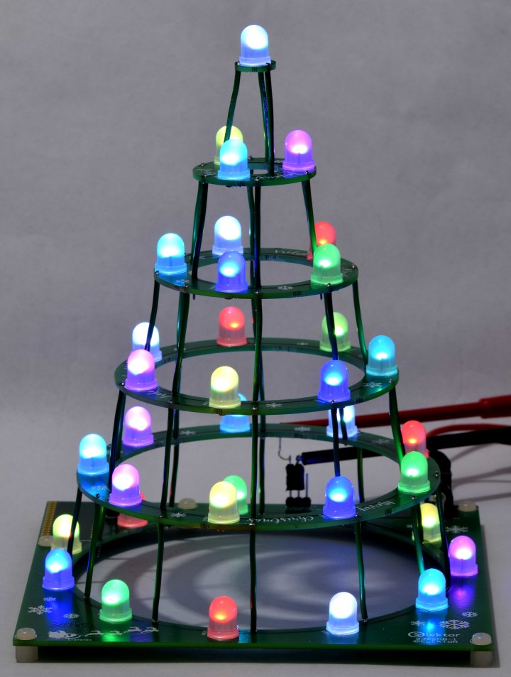
The next photos of the Circular Christmas Tree don’t really show the full bright color of the LEDs but still give a good impression.
Figure 5. Side view of the Circular Christmas Tree with the Arduino Nano ESP32 module mounted.
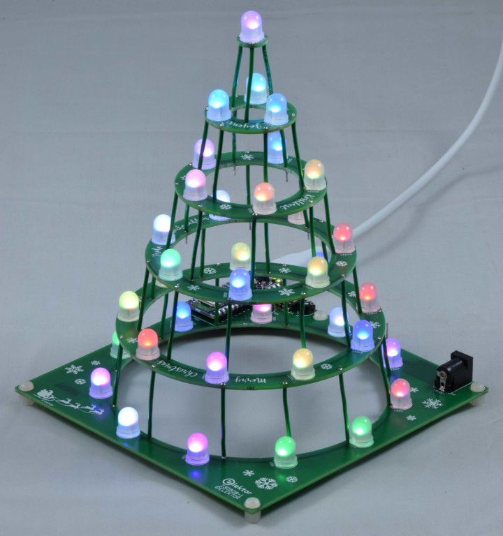
Figure 6. View from the other side of the Circular Christmas Tree with the Arduino Nano ESP32 module mounted.
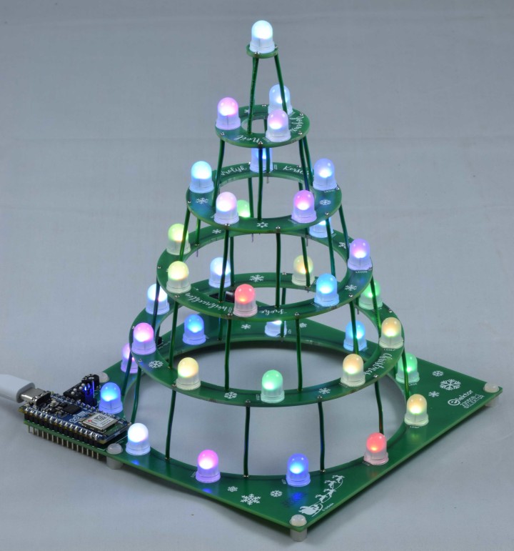
Figure 7. Another view of the of the Circular Christmas Tree with the Arduino Nano ESP32 module mounted.
Software
Among the Project Elements is the MicroPython program main.py (zipped). It’s specifically designed for this Circular Christmas Tree with MOD1 fitted. I’m an analog designer and so thank you Clemens for professionalizing the software. My program contained 264 lines, main.py now contains 110 lines. To use this program use the Arduino MicroPython Installer program to install MicroPython on the Arduino Nano ESP32. Next is to save the main.py program onto MOD1 using Arduino Lab for MicroPython. On the Arduino website about the Nano ESP32 all information can be found how to do this.The program is an example how to make different patterns, selected with dipswitch S1. Trimmer P1 is used to set the brightness of the LEDs, from 0 to maximal.
In main.py the following modes can be selected
(Mode 0 is all dipswitches set to 0. Mode 7 is S1-1, S1-2 and S1-3 set to 1, S1-4 set to 0)
Mode S1:
0: all 36 LEDs the same color, first red, next green-blue-yellow-magenta-cyan-white, then red
again and so on
1: all LEDs red
2: all LEDs green
3: all LEDs blue
4: all LEDs yellow
5: all LEDs magenta
6: all LEDs cyan
7: all LEDs white
8: colors red-green-blue-yellow-magenta-cyan-white shift continuously in sequence through all the LEDs
9: all LEDs get the same color, next color is random
10: all LEDs change color, the colors are random
So there’s still room for 4 extra modes. How about all LEDs on one PCB get the same color, but each PCB a different color? And many more patterns are possible. If you’re looking for a fun MicroPython project using a ESP32 this may be the one for you. But also software from other projects that use a ESP32 can be incorporated in the software or transferred to this Circular Christmas Tree. Look for instance at the software of project 160112 Wearable Wi-Fi Gadget (https://www.elektormagazine.com/articles/wearable-wifi-gadget). In Home Assistant a number of color effects are standard incorporated, some with a funny twinkle effect. You could set up a whole forest you can turn on or off and change effects and add whatever you can think of.
Specifications
(Module MOD1 not installed)| Power supply voltage K2 | +4.5…+5.5 V |
| Max. supply current (all LEDs and all colours set to maximum) | 1.2 A (theoretically 1.3 A, 36x3x0.012A) |
| Min. supply current (all LEDs and all colours off) | 18 mA |
Web links
Arduino Lab for Windowshttps://github.com/arduino/lab-micropython-editor/releases/download/0.8.0/Arduino.Lab.for.Micropython-win_x64.zip
Arduino MicroPython Installer
https://github.com/arduino/lab-micropython-installer/releases/tag/v1.2.1
MicroPython course MicroPython 101 by Arduino
https://docs.arduino.cc/micropython-course/
Documentation about the Arduino Nano ESP32
https://docs.arduino.cc/hardware/nano-esp32
Arduino Nano ESP32 with headers
https://www.elektor.com/arduino-nano-esp32-with-headers
Bill of Materials
ResistorR1-R36 = 75 Ω, 0W125, 5 %, SMD 0805
P1 = 10 kΩ, 0W1, 20 %, trimmer, top adjust, 6 mm round (Piher PT6KV-103A2020)
Capacitor
C1-C36 = 100 n, 50 V, 5 %, X7R, SMD 0805
C37, C38 = 47u, 6V3, 10 %, tantalum, Case Size A (1206)
Semiconductor
D1, D2 = S5J-E3/57T, SMD Case Size SMC
LED1-LED36 = WS2812D-F8, 8 mm, THT
MOD1 (optional) = Arduino Nano ESP32 with headers
Other
K1, JP1 = Pin header, 3x1, vertical, pitch 2.54 mm
JP1 = shunt jumper, 2.54 mm spacing
K2 = MJ-179PH (Multicomp Pro), DC Power Connector, 4 A, Pin Diam. 1.95 mm
S1 = DIP switch, 4way
PA1-PE6 = 2 m wire, 0.81 mm solid, 0.52 mm2 / 20AWG, insulated green (Alpha Wire 3053/1 GR005)
H1-H5 = Nylon standoff, female-female, M3, 5 mm
H1-H5 = Nylon screw, M3, 5 mm
Misc.
PCB 230508-1
Extract from construction manual
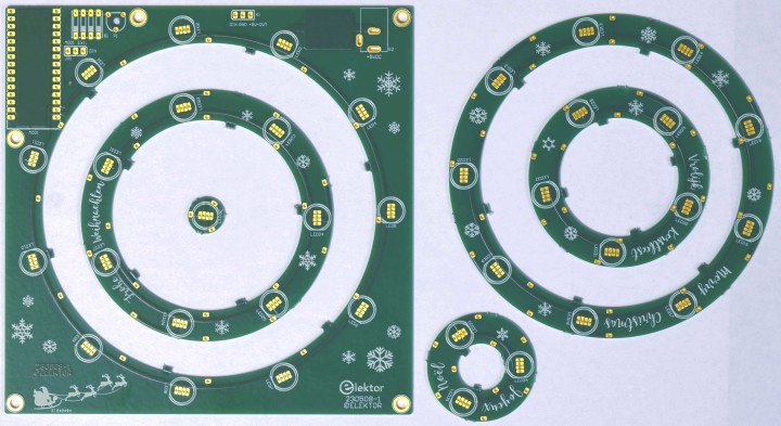
Following is an extract from the construction manual. The manual can be downloaded from our shop (www.elektor.com) once the kit of this Circular Christmas Tree is available.The PCB of the Circular Christmas Tree is a panel and the 5 circular PCBs must be removed from the base PCB by breaking the connections between the individual PCBs.
Figure 8. All PCBs separated. The bridges that connected the 6 PCBs can now be removed.
After separating the PCB's the SMD components can be soldered. Figure 9 shows all SMD components soldered and the PCBs positioned as they must be connected.
Figure 9. All SMDs soldered: R1..R36, C1..C38 and D1 and D2.
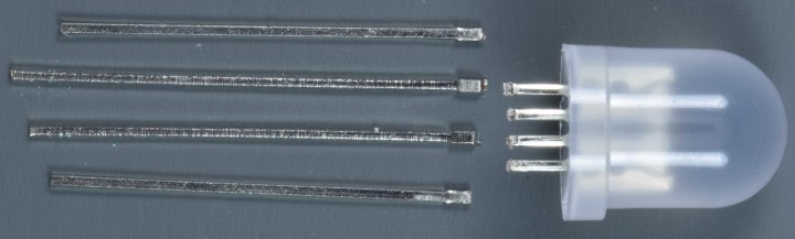
The distance between the leads of the WS2812D-F8 LEDs is very small. To make soldering the LEDs easier the holes are just big enough, more copper for 4 the pads, for the thin part of the leads to fit through. To mount the body of the LEDs against the PCBs the leads of all the LEDs have to be cut before soldering, as figure 10 shows.
Figure 10. The leads of RGB LED WS2812D-F8 cut just above the widening.
Now the 36 LEDs can be soldered.
Now the 36 LEDs can be soldered.
Figure 11. All LEDs soldered.
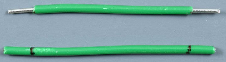
In total 39 pieces of wire connect the PCBs. Cut all wires to a length of 4 cm and strip 5 mm of the insulation at both ends. The 3 cm insulation left of all 39 pieces of wire should be as equal as possible. The length of the insulation ensure the PCBs are mounted perfectly parallel to each other.
Figure 12. One wire marked and another one stripped. Insulation left should be 3 cm long.
Figures 13 through 16 show the overlay and copper on top and bottom of PCB 230508-1 v1.1.
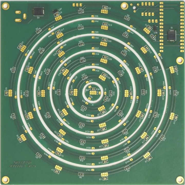
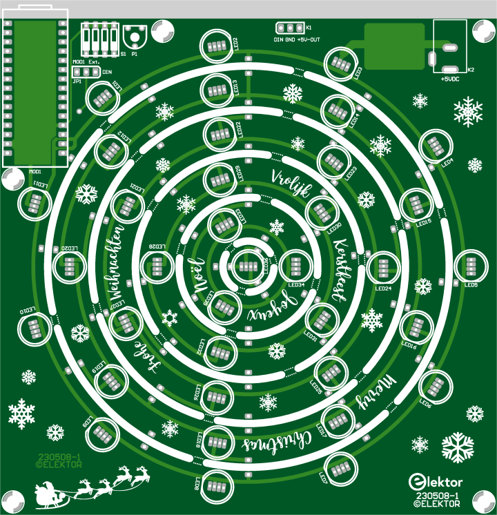
Figure 13. Top overlay of the PCB of the Circular Christmas Tree 2023 – PCB 230508-1 v1.1
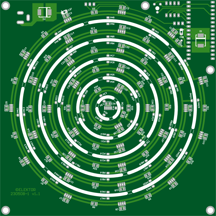
Figure 14. Bottom overlay of the PCB of the Circular Christmas Tree 2023 – PCB 230508-1 v1.1
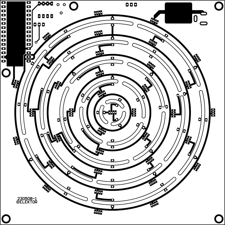
Figure 15. Copper top of the PCB of the Circular Christmas Tree 2023 – PCB 230508-1 v1.1
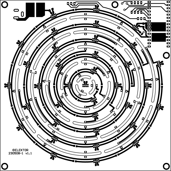
Figure 16. Copper bottom of the PCB of the Circular Christmas Tree 2023 – PCB 230508-1 v1.1
Want to build a project?
Bring your design to life with the Elektor PCB Service, powered by Eurocircuits. Upload the project files and order professionally manufactured PCBs or assembled boards through a proven European production platform.
Supporting KiCad, Eagle, Gerber, and ODB++ formats, the service is suitable for everything from prototypes and validation builds to series production and volume manufacturing.
Made in Europe. Fast. Reliable. Professional.
Discussion (6 comments)