
Design Rewind: DIY Air Quality Monitoring, Transistor Testing, and More
June 6, 2023
on
on
Elektor has been publishing innovative design projects and engineering tutorials since 1961. Check out the following projects from past June editions of Elektor Mag. These projects and articles are sure to inspire you to start a new design project of your own. Once you start a new design, be sure to share your progress on the Elektor Labs platform!
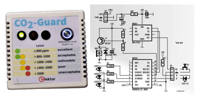 “The heart of the schematic shown in Figure 1 is MOD2, a Wemos D1 Mini, which is an ESP8266EX-based Wi-Fi module with 4-MB flash program memory,” the designers explained. “It collects data from an MH-Z19C CO2 sensor (MOD1) via a software UART, drives three LEDs to indicate CO2 levels (LED1…3), and controls buzzer BZ1, which serves as acoustic alarm when the CO2 level is unacceptably high.”
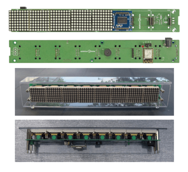 The schematic features four blocks: 3.3-V power supply; ESP-12 Wi-Fi module; Eight LED matrix displays; and components not to be mounted (block outlined in blue dashed line). “Connect to the network with your mobile device, open your browser and go to the IP address 192.168.4.1,” the designers explain. “The ESP will display its web page. There you can set the text to display and set the scrolling speed and the brightness of the display. When you click on the Apply button, the new message and/or the new parameters will be sent to the display. The buzzer BZ1 beeps to confirm reception.”
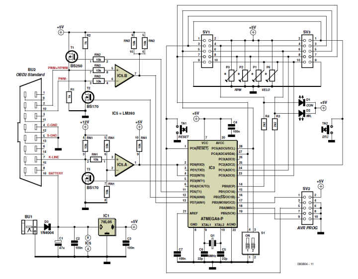 The MiniSim simulates the signals that you would normally expect to encounter when you plug an OBD analyzer into a vehicle’s OBD2 connector. It enables you to carry out testing and development of a new analyzer design from your own workbench.
"The circuit consists of a microcontroller with firmware, MOSFETs and comparators to perform the necessary voltage level shifting (5 V/12 V). The pots allow control of the simulated vehicle speed and engine rpm."
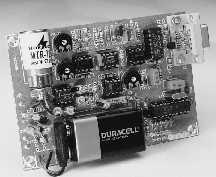
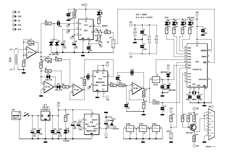 "The circuit is a combination of analogue and digital components. The audio input signal reaches input amplifier IC1a via a line transformer, Tr1. This is included for electrical isolation and to keep digital noise (8-MHz ST6 clock) away from the receiver. Preset P1 allows an output level of 2.3 V to be set. The opamp output signal is sent to a PLL (phase-locked loop), IC2, and a rectifier/buffer, IC1b-IC4a, which is followed by a filter built around IC3 and IC4b."
“The Internet is a public network, which means that it is accessible to everyone. Connecting to the network is possible in a number of ways, as indicated by the large number of advertisements in computer magazines. Internet service providers such as CompuServe, Euronet, XS4All and Surfnet function as an intermediary between the Internet and the user, in other words, they offer access to the Internet to anyone with a computer and the appropriate software. As might be expected, the charges for this service depend strongly on the services offered.”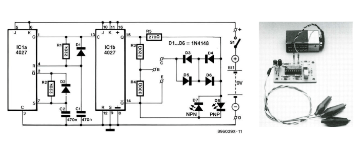 Refer to the nearby circuit and photo. "Transistors that are good are marked by only one LED (pnp or npn) lighting," Rigby explained. "All other indications (both LEDs on or off simultaneously) point to a faulty device."
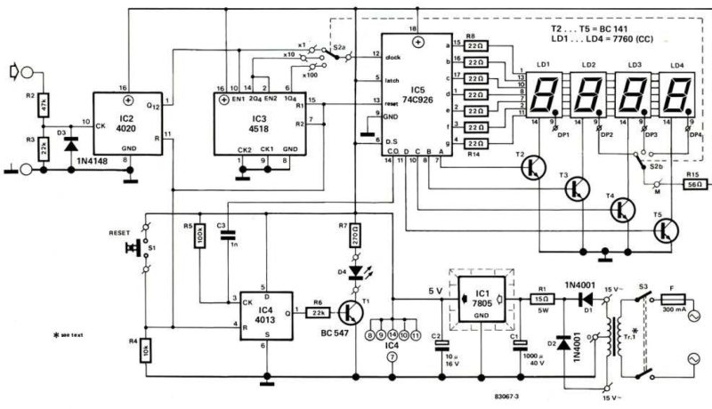
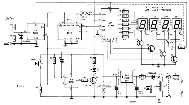 The pulses generated by the VCO are applied to the input. The meter range is increased by connecting a further divider (1C3) between the input and counter 105 by means of range switch S2. LED D4 lights up when the counter has reached its maximum capacity.
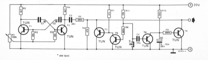
"With this circuit a tone can be produced whose frequency depends on the setting of P1 and on the values of C1 and C2. The values for these capacitors can be determined by experiment; they will generally be chosen in the range 1 . . . 10 n. If several of these stages are interconnected via resistors, a simple synthesizer can be built."
CO2 Guard: Monitor Air Quality (May/June 2022)
In May/June 2022, we presented the CO2 Guard, a DIY project for indoor air monitoring and the assessment of air quality based on the carbon dioxide concentration. The device uses an NDIR sensor and displays the air quality in five ranges on a triple LED scale. An alarm sounds if the CO2 concentration is unacceptably high. It is possible to transfer the measured values via Wi-Fi (CO2 value and temperature) to the ThingSpeak IoT analytics platform and evaluate the data graphically. Subscribe
Tag alert: Subscribe to the tag Elektor Classics and you will receive an e-mail as soon as a new item about it is published on our website! Scrolling Message Display (May/June 2018)
Looking for a fun intermediate-level project? This one will take about 3 hours. The Scrolling Message Display project enables you to scroll text on a bank of eight 8 × 8 LED matrix displays. The design features an ESP-12F (based on the ESP8266), which is programmable with the Arduino development environment. You can use a Wi-Fi-enabled device that uses Wi-Fi to send to an ESP8266 web server the text to display, the scrolling speed, and the brightness.OBD2 Mini Simulator (June 2010)
Back in June 2010, Folker Stange and Erwin Reuss presented the MiniSIM OBD simulator, which was an affordable unit that simulates communication from a vehicle’s OBD port and could communicate using four of the most popular OBD protocols."The circuit consists of a microcontroller with firmware, MOSFETs and comparators to perform the necessary voltage level shifting (5 V/12 V). The pots allow control of the simulated vehicle speed and engine rpm."
Weather Satellite Decoder (June 1999)
Weather-related applications have long been featured in the pages of Elektor Mag. Back in June 1999, we presented J. Altenburg's interesting weather-satellite decoder design, which sits between the output of a weather satellite receiver and a PC. How does it work? Featuring a PLL, extensive filtering, and a microcontroller for time-critical functions, the design translates demodulated audio signals into a serial data stream that can be processed by many image processing programs. Subscribe
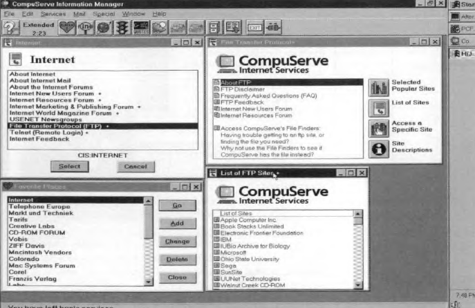
Tag alert: Subscribe to the tag circuit design and you will receive an e-mail as soon as a new item about it is published on our website! The Internet: What Is It? (June 1995)
What is the Internet? That might be silly question today, but back in 1995, it was on the mind of engineers, makers, and students around the world. Always interested in being trend aware, Elektor’s editorial team took on the question and provided this interesting article.“The Internet is a public network, which means that it is accessible to everyone. Connecting to the network is possible in a number of ways, as indicated by the large number of advertisements in computer magazines. Internet service providers such as CompuServe, Euronet, XS4All and Surfnet function as an intermediary between the Internet and the user, in other words, they offer access to the Internet to anyone with a computer and the appropriate software. As might be expected, the charges for this service depend strongly on the services offered.”
In-Circuit Transistor Tester (June 1989)
Back in 1989, author A. Rigby needed a simple, inexpensive solution to test transistors, so he designed a solution. Curious how he did it? Check out the article.DIY Energy Meter (June 1983)
Energy has been a top topic in the pages of Elektor for decades. For example, in June 1983, we presented an extension to the Elektor Energy Meter. The initial design, a watt-hour meter, helped users determine the cost effectiveness of energy-saving measures. In the June 1983 article, Elektor explained how to expand the original design into a kilowatt-hour energy meter.String Sound Generation (June 1975)
Simple can be beautiful. For instance, in June 1975, Elektor presented a simple circuit that could generate the sound of a vibrating string. An astable multivibrator, consisting of transistors T1 and T2, produces the tone."With this circuit a tone can be produced whose frequency depends on the setting of P1 and on the values of C1 and C2. The values for these capacitors can be determined by experiment; they will generally be chosen in the range 1 . . . 10 n. If several of these stages are interconnected via resistors, a simple synthesizer can be built."
Want More Design Projects?
In the coming weeks, we will highlight more classic Elektor projects, articles, and engineering tutorials. If you have any ideas, questions, or feedback, please share your thoughts in the comments section below. Share your design projects on the Elektor Labs platform!Read full article
Hide full article
Discussion (2 comments)