
Funny Bird: A Chirping Elektor Classic
on
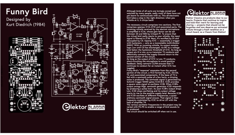
Like the “One-Armed Bandit,” also featured in the Elektor Circuit Special 2023 edition, “Funny Bird” is from Elektor’s 1984 Summer Circuits edition published in the glory days of the 4000-series CMOS logic ICs, especially the type 4093! Both little projects were given a technical makeover without compromising their original component use and look and feel too much. Almost 40 years on, lo and behold, both are now Elektor Classics!
Whistle and Harken
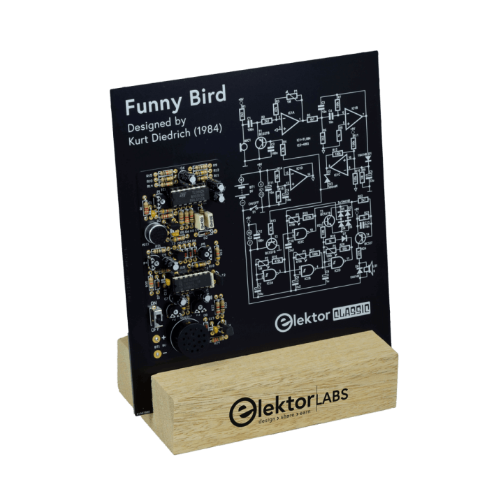
To make Funny Bird chirp back at you, set the PCB in the wooden holder and switch on the circuit. Whistle not too far from the microphone and marvel at the birdlike sound returned through the little loudspeaker. If necessary, adjust the trimpots on the board for the best experience. “Look, Mom — No DSP or AI inside!”
How It Works
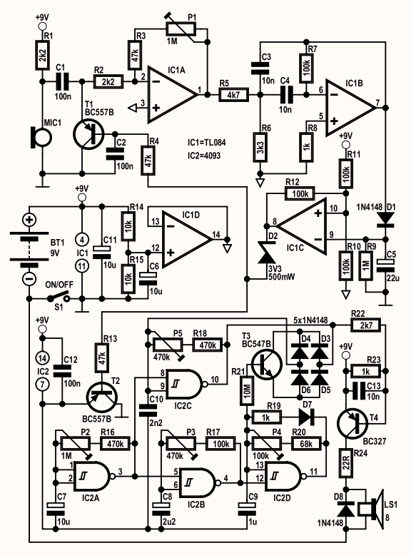
Let’s take a look at the circuit diagram in Figure 1, drawn in great Elektor style and unsurpassed by any competing magazine. The circuit comprises two sections. The first is actually opamps IC1A…IC1D and associated parts. The incoming whistle received by the electret microphone is amplified in IC1A, whose gain factor can be set between 20 and 500 by trimpot P1. To ensure that the virtual bird really reacts to your whistle, the input signal is filtered in IC1B. Next, it’s rectified by D1 and decoupled by C5. Opamp IC1C — essentially a trigger with hysteresis — acts as a monostable multivibrator (MMV). With an incoming whistle, its output remains logic Low until C5 has discharged, via R8, to a voltage level below the hysteresis threshold of IC1C. As long as output pin 8 is Low, p-n-p transistor T2 conducts and effectively connects the supply Ground return to the second section of the circuit.
controlled oscillators in a VCO configuration, triggered by whistling into
an electret microphone
Since the opamp package IC1 requires a symmetrical supply voltage, IC1D is wired as an impedance inverter to produce half the supply level, which is applied to the other opamps. As long as the output of IC1C is low, T1 conducts, short-circuiting the microphone to avoid positive feedback. Delay network C2/R4 ensures that T1 continues to conduct for an instant after IC1C has toggled.
Funny Bird’s “response” emanates from the second section of the circuit, a VCO formed by IC2C, D3…D6, T3, and associated components. If the base of T3 is fed with a sawtooth pulse of a few hertz, a chirping noise is produced. The sawtooth signal is generated by Schmitt trigger NAND gates IC2A-B-D. IC2A provides a square wave signal to oscillator IC2B. When IC2B’s output swings High, sawtooth generator IC2D responds by producing a pulse train. As soon IC2B’s output drops Low, IC2D stops oscillating and its output voltage starts to rise to the positive supply level. Because IC2B and IC2D oscillate at different frequencies, a quasi-arbitrary sawtooth signal ensues. That signal is then frequency-modulated by IC2C to drive LS1 with the help of amplifier T4.
The various oscillator frequencies in the project may be varied using P2…P5 to enable a range of bird chirps. Starting with all pots at mid-position, you’ll soon discover that finding your favorite bird sound is trial-and-error, courtesy of the 4093 IC.
The standby current consumption from the 9 V battery is around 10 mA, mainly depending on the TL084 brand. The circuit should be switched off when not in use.

Building the Chirper
Basically, everything to know about building up these Elektor Classics kits is found in the “One-Armed Bandit” article. Although the Funny Bird PCB is larger than the other two Classics published so far (One-Armed Bandit and US-Style Siren), it’s all plain sailing, as everything is contained in a kit you can buy from the Elektor Store. No worries, you’ll be soldering through-hole (TH) parts only, no tiny SMD parts which fly off at a whiff of air and keep disappearing in the vacuum cleaner. Figure 2 shows the artistically styled PCB layout.
This article (230153-01) appears in the Elektor Circuit Special 2023. Kurt Diedrich designed the original project. Ton Giesberts managed the PCB design and adaptation.
Discussion (2 comments)