
Small Circuits Revival (36): Acupuncture Meter
on
Acupuncture Meter
Idea: Elex Team
In acupuncture, diseases are treated by administrating highly targeted stimuli. This is done with thin needles that are pricked along so-called meridians in carefully chosen places. Those meridians (through which the "life energy" is said to flow) are somehow linked to the organs in the body.
The major problem with acupuncture is that these meridians have never been anatomically proven, and that this very old healing method seems to work mainly for ailments that would also have been cured without treatment. In cases such as acute appendicitis, it is therefore advisable to look for a "classically" trained healthcare professional instead of an "alternative." Be that as it may, with the conductivity meter in Figure 1, you can try to find those meridians (or, of course, take other less esoteric measurements).
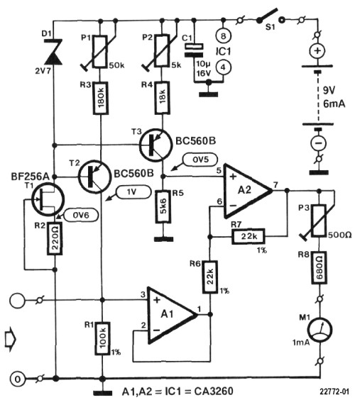
Parallel to R1 (a 1% reistor!) is the resistance of the skin (between the tips of two measuring pins). Proportionally, the voltage across the resistor will vary. (After all, the current will remain constant while the total resistance value changes.) This voltage is buffered by op-amp A1 and then goes to the minus input of op-amp A2.
The plus input has a reference voltage of 0.5 V; which is obtained by driving a constant current of just under 0.1 mA through resistor R5. On the output of op-amp A2 the difference between the output voltage of A1 and the reference voltage. This voltage is visualized by moving-coil meter M1 in such a way that we get an indication of the conductivity between the measuring pins: the greater the conductivity, the smaller the resistance between the measuring pins, the greater the differential voltage and thus the greater the deflection. .
Adjust the acupuncture meter meter before you use it. This only requires a high-resistance voltmeter — any good digital multimeter can be used. The procedure is simple: measure the voltage across R1 (the probes are not connected to anything) and adjust it with P1 to exactly 1 V. Then turn P2 until the meter does not deflect (or adjust the voltage across R5 with P2 to exactly 0.5 V). Then short the input (with a piece of wire between the measuring pins) and set P3 so that the meter is at full-scale deflection. Repeat this adjustment a few times.
Don't forget: the circuit may only be powered from a battery (9V)!
Discussion (0 comments)