

My Journey into the Cloud (15): Actuator board with the ESP8266
April 20, 2017
on
on
In the last installment of this series, we developed a small sensor node based on the Pretzel board (equipped with an ATmega and ESP8266 WiFi chip), which transmits measurement values via MQTT to the Internet. An RGB LED is used as a status indicator for the process: Yellow indicates a connection attempt ongoing; green indicates success and red indicates an error. Remember, the ESP8266 must first log into a WiFi network (note that the SSID and password are hard-coded in the Arduino sketch for the ATmega). A press of the button connects the chip via TCP / IP to the HiveMQ-MQTT test broker on the Internet. Once this has been established MQTT commands can be sent. Don’t forget before you can publish any news (Publish) or subscribe to news on a certain topic (Subscribe), you must first send an MQTT-Connect request, to which the broker responds with a defined sequence of bytes. Somewhat inelegantly, in the last episodes before publishing a message (containing a measurement value), we reset the TCP / IP connection, re-established it, and sent a new Connect request. Now in this installment - in which we will essentially send no data, only receive - we will keep the connection established.
In the last episode, I had tried subscribing to a message stream and receiving data, and for this I added to my small MQTT library with the functions
Int MQTTClient_Subscribe (String topicfilter)
Int MQTTClient_Get (byte MQTTBytesPayloadBuffer [])
Using the first function, we can subscribe to a single topic and at the same time to a variety of topics, using wildcards in the topicfilter parameter. As an MQTT client we must periodically call the second function to see whether any messages under the subscribed topic have arrived. These messages are received via TCP / IP from the MQTT broker. The broker simple relays the message bytes it receives from clients subscribed to this topic. This is made up of not only the topic and the user data, but all bytes 1: 1, including the Publish command byte and the message byte count. This simple relay procedure relieves the broker of any time-consuming transcoding and at the same time makes it very easy to extract the user data. The MQTTClient_Get function copies the user data into the byte array MQTTBytesPayloadBuffer [] (which is provided by the MQTT-Lib and also used as the send buffer).
Next it was time for a small demo application: The aim was to switch a digital actuator over the Internet. The hardware from the last sequences (see circuit given in part 13), consisting of the Pretzel board on a plug-in board, a button and the RGB-LED, I left untouched. As I am on Easter holiday (poor excuse I know), I am feeling a bit lazy so I just used D13 as a switched output and the (on / off) status of the actuator is displayed by the blue LED D3 on the Pretzel board. You can download the code of the Arduino sketch Actor_ESP8266_Ref below. In the setup function, almost everything is as usual: After the operating voltage has been applied, the ESP8266 logs into a WiFi network and lights up the RGB LED green if successful. Now you have to press the button on the plug-in board again to turn the board on (RGB-LED must first show yellow). The code now calls the ConnectAndSubscribeToTopic () function. The ESP8266 first sends a Connect request to the HiveMQ test server, followed by the Subscribe request, with the desired topic ‘/ ElektorMyJourneyIoT / TestTopic / test’. The broker should now reply with bytes 144 and 3. If these bytes are received, the RGB LED will turn green and the board will listen for data. For this the MQTTClient_Get function is called every second. The returned value indicates the number of received user bytes, which are now stored in the MQTTClient_PayloadBuffer [] array.
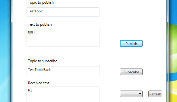
I used my very simple application protocol used in the 8th installment of this series, in which a text string ‘0000’ turns the actuator off and ‘00FF’ turns it on (not the bytes 0 and 255, but the ASCII codes for each of the four characters). I tested the whole thing with the well-known MQTT test client for the PC (see screenshot). After entering ‘TestTopic’ (the middle part of the above-mentioned topic name) in the field ‘Topic to Publish’ and ‘0000’ or ‘00FF’ in the ‘Text to publish’ field I was able to produce the switching operation by using the ‘Publish’ button.
This worked fine for just a few minutes before the connection was dropped. Looking at the MQTT specs, it became clear why this is so. In order to be able to detect any broken connections quickly, MQTT clients need to indicate periodically to the broker via TCP / IP that they are still active. The link can be kept alive by sending any sort of request or an instruction to publish something; otherwise the broker drops the connection. The so-called keep-alive time determines how long this time window is, it is determined by the client during the Connect request. In my rudimentary MQTT library this time is always set to 180 seconds.
What if, in our case, the MQTT client only listens and does not continually send messages to the broker? In this case, the client will need to periodically send a ping request (consisting of bytes 192 and 0) to which the broker responds with a ping response (bytes 208 and 0). The client can thus confirm whether the connection is still available.
I expanded my MQTT-Lib with the int MQTTClient_Ping () function which returns a 1 when successful; I call this in the application code about once every 15 seconds. Each ping attempt is indicated by a (brief) yellow flash from the RGB LED which will then light up green or red. In contrast to the sensor application from the last two installments, the connection (both TCP / IP and MQTT) remains established throughout the process.
Now the switching application remains active over a longer time; however, for the client sending the MQTT message, there is no acknowledgement indicating that the switching operation has been successful. The link could become disconnected, for example; also the message may not arrive if the actuator client has just issued a ping to the broker. My simple solution to the problem is to send a short acknowledge message from the actuator client to the switching client using an extra topic. A message from the actuator with the text ‘R1’ means that the blue LED has been successfully switched on and ‘R0’ means it has been switched off.
Try it out: With my MQTT-Testclient (in the download) you can send control messages as shown above and also receive the feedback messages. First, you need to subscribe to the topics for both message directions (‘TestTopic’ and ‘TestTopicBack’ in the ‘Topic to subscribe’ field and then press the Subscribe button). If you do not see ‘R1’ in the field ‘Received Text’ shortly after sending the text ‘00FF’, or ‘R0’, after sending ‘0000’ then this indicates that the switching command has not been processed. In this case you can send the message again using the Publish-Button.
From time to time, it can happen that we have no link - the connection is permanently down. In this case, the RGB LED will light up red on the actuator board. Pressing the button again causes the board to reconnect to the HiveMQ test server (the RGB LED will then go to yellow and then green). This sequence could, of course, also be automated and could well be the subject of the next episode. Stay tuned!
In the last episode, I had tried subscribing to a message stream and receiving data, and for this I added to my small MQTT library with the functions
Int MQTTClient_Subscribe (String topicfilter)
Int MQTTClient_Get (byte MQTTBytesPayloadBuffer [])
Using the first function, we can subscribe to a single topic and at the same time to a variety of topics, using wildcards in the topicfilter parameter. As an MQTT client we must periodically call the second function to see whether any messages under the subscribed topic have arrived. These messages are received via TCP / IP from the MQTT broker. The broker simple relays the message bytes it receives from clients subscribed to this topic. This is made up of not only the topic and the user data, but all bytes 1: 1, including the Publish command byte and the message byte count. This simple relay procedure relieves the broker of any time-consuming transcoding and at the same time makes it very easy to extract the user data. The MQTTClient_Get function copies the user data into the byte array MQTTBytesPayloadBuffer [] (which is provided by the MQTT-Lib and also used as the send buffer).
Next it was time for a small demo application: The aim was to switch a digital actuator over the Internet. The hardware from the last sequences (see circuit given in part 13), consisting of the Pretzel board on a plug-in board, a button and the RGB-LED, I left untouched. As I am on Easter holiday (poor excuse I know), I am feeling a bit lazy so I just used D13 as a switched output and the (on / off) status of the actuator is displayed by the blue LED D3 on the Pretzel board. You can download the code of the Arduino sketch Actor_ESP8266_Ref below. In the setup function, almost everything is as usual: After the operating voltage has been applied, the ESP8266 logs into a WiFi network and lights up the RGB LED green if successful. Now you have to press the button on the plug-in board again to turn the board on (RGB-LED must first show yellow). The code now calls the ConnectAndSubscribeToTopic () function. The ESP8266 first sends a Connect request to the HiveMQ test server, followed by the Subscribe request, with the desired topic ‘/ ElektorMyJourneyIoT / TestTopic / test’. The broker should now reply with bytes 144 and 3. If these bytes are received, the RGB LED will turn green and the board will listen for data. For this the MQTTClient_Get function is called every second. The returned value indicates the number of received user bytes, which are now stored in the MQTTClient_PayloadBuffer [] array.
I used my very simple application protocol used in the 8th installment of this series, in which a text string ‘0000’ turns the actuator off and ‘00FF’ turns it on (not the bytes 0 and 255, but the ASCII codes for each of the four characters). I tested the whole thing with the well-known MQTT test client for the PC (see screenshot). After entering ‘TestTopic’ (the middle part of the above-mentioned topic name) in the field ‘Topic to Publish’ and ‘0000’ or ‘00FF’ in the ‘Text to publish’ field I was able to produce the switching operation by using the ‘Publish’ button.
This worked fine for just a few minutes before the connection was dropped. Looking at the MQTT specs, it became clear why this is so. In order to be able to detect any broken connections quickly, MQTT clients need to indicate periodically to the broker via TCP / IP that they are still active. The link can be kept alive by sending any sort of request or an instruction to publish something; otherwise the broker drops the connection. The so-called keep-alive time determines how long this time window is, it is determined by the client during the Connect request. In my rudimentary MQTT library this time is always set to 180 seconds.
What if, in our case, the MQTT client only listens and does not continually send messages to the broker? In this case, the client will need to periodically send a ping request (consisting of bytes 192 and 0) to which the broker responds with a ping response (bytes 208 and 0). The client can thus confirm whether the connection is still available.
I expanded my MQTT-Lib with the int MQTTClient_Ping () function which returns a 1 when successful; I call this in the application code about once every 15 seconds. Each ping attempt is indicated by a (brief) yellow flash from the RGB LED which will then light up green or red. In contrast to the sensor application from the last two installments, the connection (both TCP / IP and MQTT) remains established throughout the process.
Now the switching application remains active over a longer time; however, for the client sending the MQTT message, there is no acknowledgement indicating that the switching operation has been successful. The link could become disconnected, for example; also the message may not arrive if the actuator client has just issued a ping to the broker. My simple solution to the problem is to send a short acknowledge message from the actuator client to the switching client using an extra topic. A message from the actuator with the text ‘R1’ means that the blue LED has been successfully switched on and ‘R0’ means it has been switched off.
Try it out: With my MQTT-Testclient (in the download) you can send control messages as shown above and also receive the feedback messages. First, you need to subscribe to the topics for both message directions (‘TestTopic’ and ‘TestTopicBack’ in the ‘Topic to subscribe’ field and then press the Subscribe button). If you do not see ‘R1’ in the field ‘Received Text’ shortly after sending the text ‘00FF’, or ‘R0’, after sending ‘0000’ then this indicates that the switching command has not been processed. In this case you can send the message again using the Publish-Button.
From time to time, it can happen that we have no link - the connection is permanently down. In this case, the RGB LED will light up red on the actuator board. Pressing the button again causes the board to reconnect to the HiveMQ test server (the RGB LED will then go to yellow and then green). This sequence could, of course, also be automated and could well be the subject of the next episode. Stay tuned!
Read full article
Hide full article
Discussion (0 comments)