
My Journey into the Cloud (17): using an ESP32 for the actuator
July 5, 2017
on
on
In installments 15 and 16 of this series, we took a step by step approach to implement a small project which shows how an LED can be switched remotely via MQTT. For the hardware we used a pretzel board with a WLAN chip ESP8266 and an ATmega328. We developed the firmware for the ATmega using the Arduino IDE. A small TCP / IP library is used to send AT commands to the ESP8266. Functions in the MQTT library are used to generate the messages sent to the MQTT test broker and to decode the replies. The application also accesses the MQTT library. The main loop checks whether control commands to switch the LEDs have been received, ping-bytes and status messages are also sent.
The ESP32 Core board
The Pretzel board is a really useful tool especially when you are starting out with networks. Now however it was time to try out a different type of board. We took a look at the ESP32 which is the more powerful cousin of the ESP8266 with many more peripheral functions built-in. In the current July / August 2017 edition of Elektor, Tam Hanna describes how this 32-bit controller board can be programmed using the Arduino IDE.
Last week the ‘ESP32 DevKitC’ boards (aka ‘ESP32 Coreboard V2’) arrived in the lab. This small development board gets its power from the micro USB socket which also serves as the programming port. Important controller signals are available at the pin header strips which come already soldered in position. After unpacking you can therefore get straight to work; plug it into a prototyping board and start wiring.
No sooner said than done; I followed step by step the procedure outlined by Tam Hanna (he uses a different board in the article but it hardly makes a difference). First, I connected the board via USB to my Windows notebook and downloaded the driver for the USB / Serial Converter CP2102 from Silicon Labs, which installs automatically. I then installed Git for Windows on my computer. After opening the program, I entered ‘https://github.com/espressif/arduino-esp32.git’ in the ‘Source Location’ field. In the Target Location field, enter the path where the Arduino-IDE application files reside, plus ‘\ hardware \ espressif \ esp32 ‘ (in my case, the entire path is C: \ Users \ jensn \ Documents \ Arduino \ hardware \ espressif \ esp32). After the files have been downloaded with Clone (the window that pops up at the end, can simply be closed) I called the get.exe program in the newly created subfolder ... \ espressif \ esp32 \ tools to transfer the remaining files to my computer.
WiFi and WiFiClient
In the Arduino IDE, I selected the ESP32 Dev Module as the target and selected the correct COM port. Now we can start with the first program. When I tried to upload my first sketch I was greeted with the message "the selected serial port failed to execute script esptool does not exist or your board is not connected". This indicated an issue with the port so I connected the board directly to my notebook instead of via a USB hub and the error was resolved.
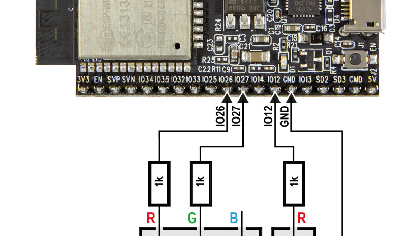
The ESP32 DevKitC is not fitted with a user LED but it is easy to mount one on the plug board. A red LED is connected to pin IO12 (with a 1 kΩ resistor to earth) so that it can be switched on using the familiar Arduino GPIO commands:
pinMode (12, OUTPUT);
digitalWrite (12, HIGH);
Next, I tested the simple LED flash program given in the 7-8 / 2017 edition of Elektor. In this article by Tam Hanna it goes on to show how a sawtooth waveform is generated and after this comes the first reference to a network command:
#include <WiFi.h>
You can make your own sketch accessible to the classes WiFi and WiFiClient, which provide easy-to-understand functions. The line
WiFi.begin (txtSSID, txtPassword);
Instructs the ESP32 to connect to a home network
WiFi.status () == WL_CONNECTED
Allows you to find out if the connection was successful. After this
WiFiClient client;
Creates a WiFiClient object which can be used with commands such as client.connect(URL, port), client.write(buf, len), and client.readBytes(buf, len) as well as to connect to a server over TCP / IP for sending and receiving bytes. It’s not necessary to concern yourself with AT commands or any other internals of the ESP32, slowly I am beginning to appreciate the Arduino system.
Porting to the ESP32
Now we get to the part I’ve been looking forward to where we actually get the MQTT actuator project running on an ESP32. As a base for the software I use the sketch we developed in the last installment. First I took care of the TCP / IP functions, replacing the AT commands for the ESP8266 with calls to the WiFiClient equivalent functions (I made one small change to the library: TCPClient_Connect function now returns a negative value instead of a 0 when an error is detected). Next I modified the setup function, where the chip gets configured to connect with my Wi-Fi network (also here I could replace the AT commands with the WiFi functions mentioned above).
Finally, I connected the RGB LED to the ESP32 DevKitC (see schematic in the picture, on the Internet you can also find a useful page which sets out the functions of the pins). I made use of the user pushbutton on the board which is positioned to the right of the Micro-USB socket and connected to GPIO0 according to the ESP32 DevKitC circuit diagram. It was also necessary to change the pin definitions in the code (the pushbutton pin is also specified twice more in the code, which I will tidy up at the next opportunity). These were the only changes necessary; the remainder (MQTT library, main loop, application functions, etc.) was simply copied and pasted.
Errors occurred at the first compilation attempt, it was necessary to make two small changes:
1. The WiFi and WiFiClient functions require parameters of type char* instead of string.
2. Functions must be declared in the code before the first call is made.
Implementing the changes was not a problem, but I must admit the resulting listing is not the finest example of elegant code writing. In one of the forthcoming installments we will spend some time making it more ‘portability-friendly’.
In the end everything worked just as it did in the last installment of this series, which I tried with the well-known MQTT client for the PC. You can find this (as well as the Sketch ‘Actor_ESP32_Ref’) in the download for this installment. I also put the sketch for the ESP8266 back in the ZIP archive, so you can easily compare the two listings.
Standby for the next installment!
The ESP32 Core board
The Pretzel board is a really useful tool especially when you are starting out with networks. Now however it was time to try out a different type of board. We took a look at the ESP32 which is the more powerful cousin of the ESP8266 with many more peripheral functions built-in. In the current July / August 2017 edition of Elektor, Tam Hanna describes how this 32-bit controller board can be programmed using the Arduino IDE.
Last week the ‘ESP32 DevKitC’ boards (aka ‘ESP32 Coreboard V2’) arrived in the lab. This small development board gets its power from the micro USB socket which also serves as the programming port. Important controller signals are available at the pin header strips which come already soldered in position. After unpacking you can therefore get straight to work; plug it into a prototyping board and start wiring.
No sooner said than done; I followed step by step the procedure outlined by Tam Hanna (he uses a different board in the article but it hardly makes a difference). First, I connected the board via USB to my Windows notebook and downloaded the driver for the USB / Serial Converter CP2102 from Silicon Labs, which installs automatically. I then installed Git for Windows on my computer. After opening the program, I entered ‘https://github.com/espressif/arduino-esp32.git’ in the ‘Source Location’ field. In the Target Location field, enter the path where the Arduino-IDE application files reside, plus ‘\ hardware \ espressif \ esp32 ‘ (in my case, the entire path is C: \ Users \ jensn \ Documents \ Arduino \ hardware \ espressif \ esp32). After the files have been downloaded with Clone (the window that pops up at the end, can simply be closed) I called the get.exe program in the newly created subfolder ... \ espressif \ esp32 \ tools to transfer the remaining files to my computer.
WiFi and WiFiClient
In the Arduino IDE, I selected the ESP32 Dev Module as the target and selected the correct COM port. Now we can start with the first program. When I tried to upload my first sketch I was greeted with the message "the selected serial port failed to execute script esptool does not exist or your board is not connected". This indicated an issue with the port so I connected the board directly to my notebook instead of via a USB hub and the error was resolved.
The ESP32 DevKitC is not fitted with a user LED but it is easy to mount one on the plug board. A red LED is connected to pin IO12 (with a 1 kΩ resistor to earth) so that it can be switched on using the familiar Arduino GPIO commands:
pinMode (12, OUTPUT);
digitalWrite (12, HIGH);
Next, I tested the simple LED flash program given in the 7-8 / 2017 edition of Elektor. In this article by Tam Hanna it goes on to show how a sawtooth waveform is generated and after this comes the first reference to a network command:
#include <WiFi.h>
You can make your own sketch accessible to the classes WiFi and WiFiClient, which provide easy-to-understand functions. The line
WiFi.begin (txtSSID, txtPassword);
Instructs the ESP32 to connect to a home network
WiFi.status () == WL_CONNECTED
Allows you to find out if the connection was successful. After this
WiFiClient client;
Creates a WiFiClient object which can be used with commands such as client.connect(URL, port), client.write(buf, len), and client.readBytes(buf, len) as well as to connect to a server over TCP / IP for sending and receiving bytes. It’s not necessary to concern yourself with AT commands or any other internals of the ESP32, slowly I am beginning to appreciate the Arduino system.
Porting to the ESP32
Now we get to the part I’ve been looking forward to where we actually get the MQTT actuator project running on an ESP32. As a base for the software I use the sketch we developed in the last installment. First I took care of the TCP / IP functions, replacing the AT commands for the ESP8266 with calls to the WiFiClient equivalent functions (I made one small change to the library: TCPClient_Connect function now returns a negative value instead of a 0 when an error is detected). Next I modified the setup function, where the chip gets configured to connect with my Wi-Fi network (also here I could replace the AT commands with the WiFi functions mentioned above).
Finally, I connected the RGB LED to the ESP32 DevKitC (see schematic in the picture, on the Internet you can also find a useful page which sets out the functions of the pins). I made use of the user pushbutton on the board which is positioned to the right of the Micro-USB socket and connected to GPIO0 according to the ESP32 DevKitC circuit diagram. It was also necessary to change the pin definitions in the code (the pushbutton pin is also specified twice more in the code, which I will tidy up at the next opportunity). These were the only changes necessary; the remainder (MQTT library, main loop, application functions, etc.) was simply copied and pasted.
Errors occurred at the first compilation attempt, it was necessary to make two small changes:
1. The WiFi and WiFiClient functions require parameters of type char* instead of string.
2. Functions must be declared in the code before the first call is made.
Implementing the changes was not a problem, but I must admit the resulting listing is not the finest example of elegant code writing. In one of the forthcoming installments we will spend some time making it more ‘portability-friendly’.
In the end everything worked just as it did in the last installment of this series, which I tried with the well-known MQTT client for the PC. You can find this (as well as the Sketch ‘Actor_ESP32_Ref’) in the download for this installment. I also put the sketch for the ESP8266 back in the ZIP archive, so you can easily compare the two listings.
Standby for the next installment!
Read full article
Hide full article
Discussion (2 comments)