SmartScope USB oscilloscope, logic analyzer and signal generator
The SmartScope is an especially handy and affordable USB oscilloscope, logic analyzer and signal generator. It works with a Windows or Linux PC, but as well with an Android tablet, an iPad or an OS X system.
The LabNation SmartScope is an especially handy and affordable USB oscilloscope, logic analyzer and signal generator with a number of remarkable features. Most USB oscilloscopes have been designed for use in combination with a Windows or Linux PC. The SmartScope is an exception to this: it works just as well with an Android tablet, an iPad or an OS X system. The software has been designed to make the user interface appear identical across all platforms. Another big advantage is that the standard software already includes several decoders for digital signal protocols.
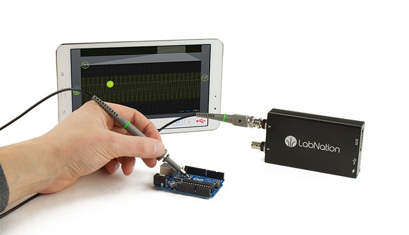
The SmartScope's hardware consists of a small metal enclosure (for good shielding), with a pair of full-sized BNC connectors on the front for the analog inputs, and a 16-pin header at the back, for the eight digital inputs of the logic analyzer, four digital outputs, and the output of the built-in arbitrary waveform generator (AWG). Also on the back are a mini- and a micro-USB connector. The mini-USB is for connecting to a tablet, smartphone or computer; the micro-USB is used to connect an external power supply.
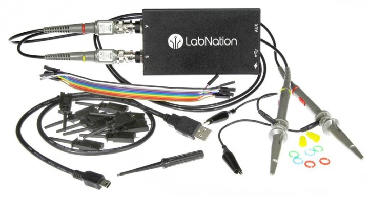
Smartscope with all accessories
The printed circuit board contains a powerful Xilinx Spartan 6 FPGA, which takes care of the main tasks (such as processing the received measurement data and creating the AWG signal). The conversion of the input signals is taken care of by an A/D converter with 100 Msamples/channel and a resolution of 8 bits. A RAM chip provides a buffer capacity of 4 Msamples/ channel. A PIC controller takes care of the communications with the computer via de USB connection. There are several relays and opamps at the inputs for the range and AC/DC selections. The bandwidth of the analog input section is 45 MHz. This is quite large compared to the sample frequency of 100 Msamples/s. This was done on purpose in order to minimize the attenuation of the input signals as much as possible. The usable input range is up to about 10 to 20 MHz (which is also stated by LabNation).
Software
One of the most important goals that the developers had in mind was that the software should run under almost any operating system, with an identical user interface. It can therefore run on a standard PC or a laptop, but also on a tablet or a smartphone.
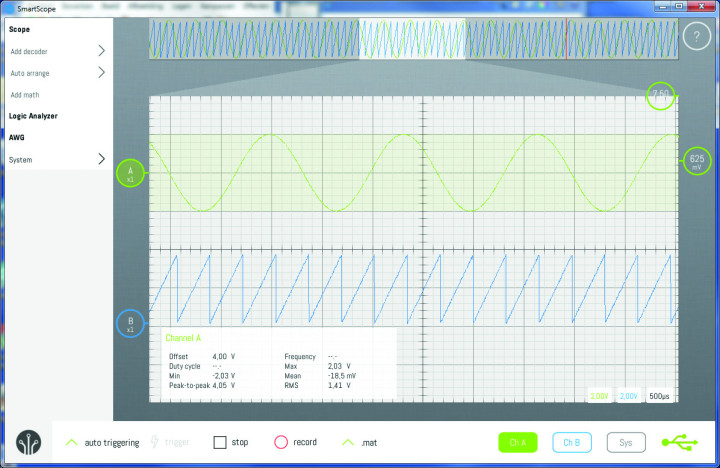
The contents of the hardware buffer can be shown at the top of the display, from where you can select a section and zoom in on it.
The developers also felt that the controls on most USB scopes were somewhat limiting. The user interface is usually some sort of copy of that found on hardware scopes, which has been in existence since the fifties. The whole control panel including the knobs is often simulated on the screen, or pull-down menus are used for all kinds of settings. This was thought to be a bit out of date, and found not to be very intuitive. The software for the SmartScope had to be different and should make use of modern interfaces such as touchscreens. The result is a control surface that reminds you of your first experience with a tablet or smartphone: it is a bit strange to start with, but it soon feels right. It’s as if you’ve given somebody their first tablet: they’ll play with it for a bit and after quarter of an hour it looks as if they’ve been using it all their life. The same happens with the software for the SmartScope. It takes a little bit of time to get used to it, but then it becomes so obvious that you don’t want to return to the old-fashioned methods.
On the left is the main menu with all the settings. At the bottom are a few of the most commonly used settings. The rest of the screen is taken up by the scope display with a scale, where the measured signals will be displayed.
These are the two analog inputs or the eight digital inputs when in the logic analyzer-mode. Wwhen one of the built-in serial decoders is used, the decoded data will also be displayed. Up to now, there’s been nothing really special. What is remarkable is the absence of control knobs and buttons. Instead of using menus and knobs, almost everything is done via mouse clicks or (in case of a touchscreen) by swiping your fingers.
This does take some time to get used to. But once you’ve found out how to change a setting (such as changing the input gain using a pinch/stretch gesture with two fingers), it soon becomes second nature. Each signal has an identically colored circle to the left of the grid, which hides a number of functions. When you touch it or click on it with the mouse a small menu appears that lets you set up the AC/DC coupling, triggering, probe attenuation or hide the signal. There is a similar circle at the right of the grid. The menu associated with this lets you select the trigger channel and either the rising or the falling edge for triggering. A status box can be displayed that shows the settings and a lot of detailed information about the signal. When it is no longer required, you can just drag it off the screen.
At the top of the display you can call up the hardware memory buffer. This shows the full contents of the buffer (4 Msamples). From here you can quickly and easily select a section that interests you so you can look at it more closely.
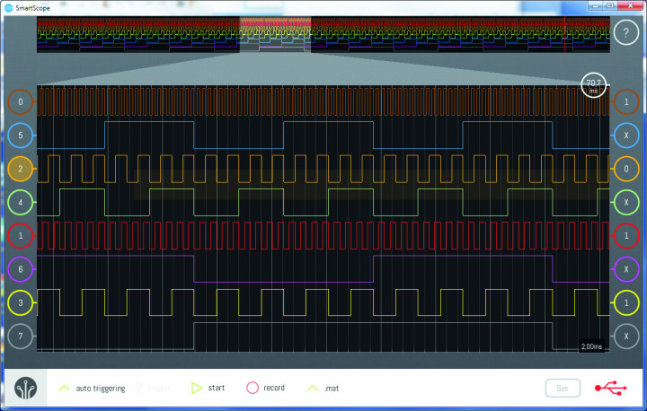
The logic analyzer with its 8 channels. You can easily access the 4 million measurements in the hardware buffer and inspect them in detail.
The menu on the left has a section that lets you set up the AWG. At the moment the user can choose from a number of standard wave forms, or import a user-defined signal from a CSV file, which can be stored in Dropbox or a local hard drive. One thing that stands out is that a number of digital decoders are included as standard with the software. It’s unusual to see this for products in this price range (you would expect to pay for these as an extra). These decoders are used to unravel different types of digital formats and to display things such as the actual values and addresses of the data. There are decoders for I²C, 3-wire and 4-wire SPI and UART included with the software. It is also possible for users to write their own decoder, and to make it available to the SmartScope community. Such a decoder consists of a single DLL file, which should be added to the SmartScope system folder. This has been set up in such a way that it can work across all platforms without modifications.
FPGA Development Platform
Internally, the SmartScope is built around a powerful Xilinx Spartan 6 FPGA, which also makes it suitable for use as an FPGA development platform. Elektor offers the unique SmartScope Maker Kit, which includes a special version of the SmartScope and two programmers with suitable cables. To allow the SmartScope to be used as a hardware platform for FPGA prototyping, LabNation has made its software and firmware stacks open-source and optimized them for this purpose. With access to the platform’s VHDL files, it is easy to compile your own FPGA code and download it to the SmartScope. Then you can control it through the USB link from a desktop, tablet or smartphone. Harry Baggen, former editor-in-chief of Elektor with a special interest in measurement equipment, published a review about the Maker Kit. There was also an article in Elektor magazine 11/2016, which is available as free PDF download.

Discussion (1 comment)