
Review: Eurocircuits Marking Editor
Opening the Marking Editor
To use the Marking Editor you must, of course, first upload a PCB design. Go to the Eurocircuits website and click Analyze Data. Fill in the form, select your gerber files and validate the form. Wait for the PCB Visualizer to do its work (when the animated busy icon is replaced by something static, preferably a green checkmark), then open it. In the left pane scroll down until you see the ‘Advanced options’ section. Next to the section’s title sits the ‘Marking’ button. Click it to open the Marking Editor.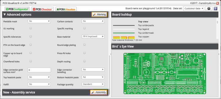
After opening the editor you will (should) notice one mark: Eurocircuit’s order number. Let’s find out what we can do with/to it, it will help us to get familiar with the editor.
Using the Marking Editor
The order number is placed automatically in a position where it is, hopefully, not in the way. However, it may happen that you wanted that space to remain mark free. Normally you would not have or be given a choice but the marking editor lets you move it. Click the red rectangle surrounding the mark to make it orange and drag it to a more suitable position. But you can do more. In the ‘Tools’ pane on the right, scroll down to the ‘Ordernumber properties’. Here you can change the layer on which the mark will be placed (copper or legend) and you can rotate it.Note that whenever your edit creates a production problem a warning message is displayed at the bottom of the ‘Tools’ pane. Correct the problem by either fixing it or by undoing your last edit.
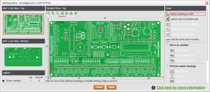
The order number mark is imposed, and each board must at least have one. By default the order number is placed on the top legend but with a trick it can be moved to the other side of the board:
- Select the other side of the board using the ‘Switch view to…’ button or click the correct ‘Bird’s Eye View’ pane on the left
- Click the ‘O/N’ button to add an extra order number
- Position & rotate it as you like, and select the copper or legend layer
- Switch view back to the other side
- Select the order number and ‘Delete the selected object’
Custom markings
Having gotten this far we understand the editor’s basic functionality and we can add custom marks. For this you must first check the ‘PCB has custom markings’ checkbox before you can do anything. Why this is necessary is not clear to me, but hey, it is only one extra click. Now you can add a production date for instance, several formats are proposed, or free text. Make sure to press Enter when you change the mark’s size.Adding a custom logo or image is really simple, all you have to do is select the image file (JPG, GIF, PNG, TIFF or BMP) and place it where you want. Custom logos can be placed on print, copper and solder mask layers, giving you potentially the option to correct the solder mask (but you did that already in your design tool). Note that logos are subject to Eurocircuits’ rules for legend printing meaning that openings in the solder mask will be clipped away.
A great option is adding a QR code. Instead of producing the QR code yourself, the Marking Editor will do this for you from the text provided by you (beware of typos!). QR codes can only be place on component print layers.
Read full article
Hide full article
Discussion (0 comments)