
ADS127L11EVM-PDK ADC Evaluation Module
January 11, 2022
on
on
24-bit, high-speed, wide-bandwidth ΔΣ ADC
Texas Instruments ADS127L11EVM-PDK ADC Evaluation Module (EVM) performance demonstration kit (PDK) is a platform for evaluating the ADS127L11. The ADS127L11 is a 24-bit, high-speed, wide-bandwidth, delta-sigma (ΔΣ) analog-to-digital converter (ADC). The Texas Instruments ADS127L11EVM-PDK includes the ADS127L11 evaluation board, precision host interface (PHI) controller board, and accompanying computer software. This PDK lets the user communicate with the ADC over a universal serial bus (USB), capture data, and perform data analysis.
Features
- Includes hardware and software required for diagnostic testing, as well as accurate performance evaluation of the ADS127L11 ADC
- Ships with PHI controller board, which provides a convenient interface to the EVM over USB 2.0 (or higher) for power delivery and digital interface
- No external power supply required
- Easy-to-use evaluation software for Windows® 8/10 64-bit operating systems; software suite includes a graphical tool for data capture and analysis
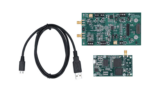
Kit Contents
- ADS127L11 evaluation module
- PHI controller board
- USB Micro-B plug to USB-A plug cable
The ADS127L11EVM board includes the following features:
• External signal source from differential pair SMA connectors• Options to use external analog and digital power supplies
• Serial interface header for easy connection to the PHI controller
• Pin connections to monitor digital signals with a logic analyzer
• Onboard ultra-low noise, low-dropout (LDO) regulator for excellent 5-V, single-supply regulation of all analog circuits
The ADS127L11EVM is designed for easy interfacing with analog sources. For best performance, differential analog input signals can be connected through the SMA connectors (J3 and J6). There is also a header, J4, that can be used to directly connect inputs for dc measurements, or where best ac performance is not needed. For single-ended inputs, header J4 can be used to connect AINN or AINP to GND using the supplied shunt. Then use either J3 or J6 as the single-ended input. The input driver circuit uses the THS4551 fully-differential amplifier in a unity-gain configuration with a single-pole RC filter at the output.
Multiple passive components around the amplifier are intentionally left uninstalled to give users the flexibility to customize the input drive circuit for their specific application. When differential inputs are connected to the SMA connectors (J3 and J6), make sure header J4 does not have any connection to pins 1 or 3. Only connect the included shunt to pin 2, and not between pins 1-2 or 1-3 for differential inputs.
Learn more >>>
Read full article
Hide full article
Discussion (0 comments)