
Microchip Technology's AVR-IoT and PIC-IoT Dev Boards
on
As you already should know, Microchip Technology acquired Atmel in 2016 and now offers the PIC® series of microcontrollers (MCUs) and the Atmel lineup including the AVR® MCU series. Microchip continues to offer and expand the AVR series to add new features and functions for its customers. This means that products and evaluation boards will now get the best of all products that are offered by Microchip. Therefore, we would like to introduce you to the Microchip AVR-IoT and PIC-IoT WA Development Boards for Wi-Fi connection to Amazon Web Services (AWS) IoT Core.
Taking your fist steps into the world of cloud storage and computing for your data can be tricky. Operating on limited power while establishing a secure data transmission to a cloud service like AWS can be challenging for developers. Microchip offers two development boards that will give you access to the AWS IoT Core and provide a way to establish a secure communication over Wi-Fi while keeping the amount of energy used low and shorten your development time. Before diving into the hardware and software details, let’s first look at what is in the box and what we can expect.
What’s inside the PIC-IoT and AVR-IoT boxes?
We have two boxes indicating what should be inside (Figure 1).
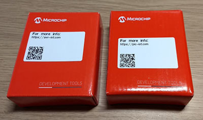
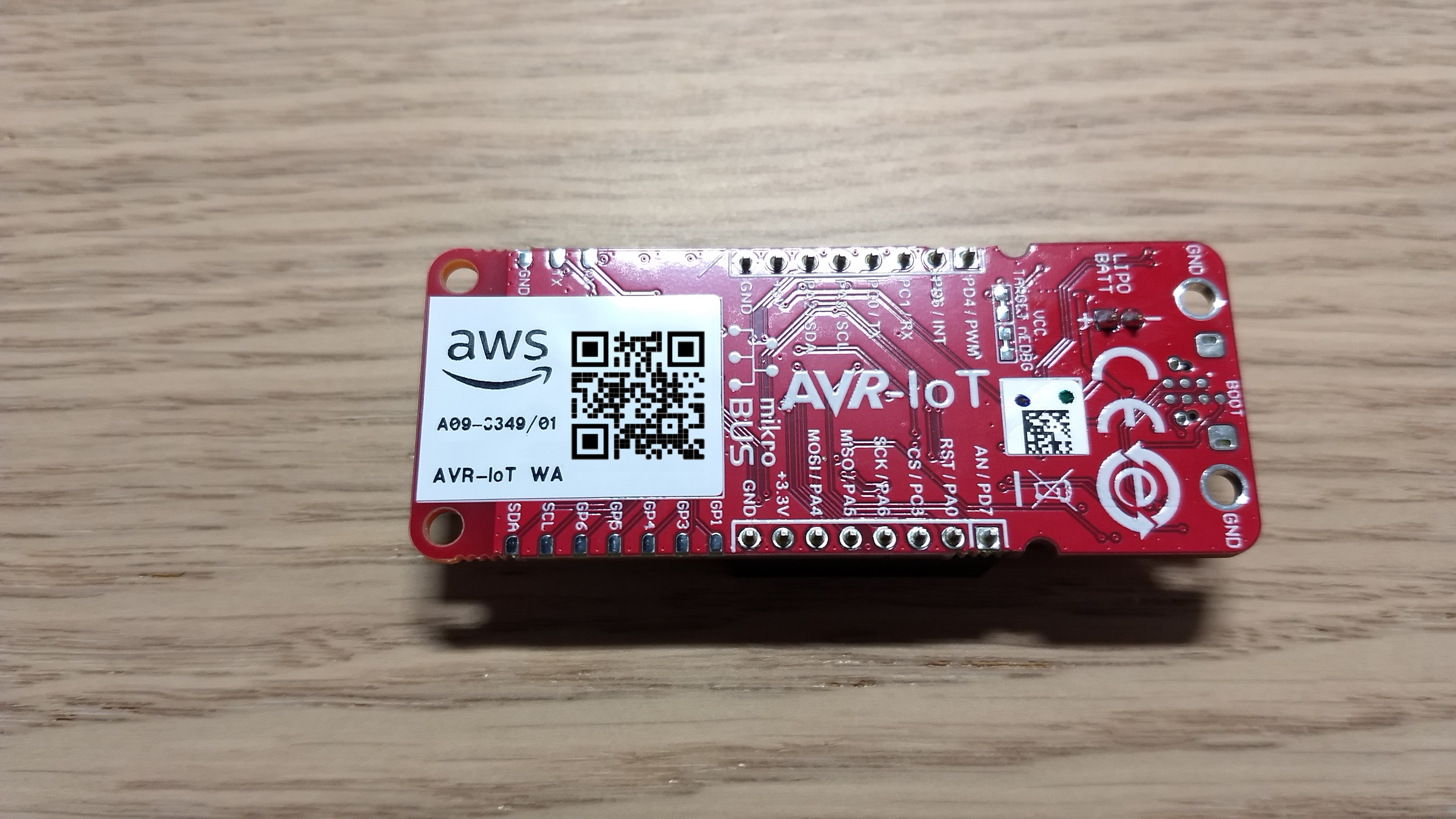
As most will have a micro-USB cable at hand, those are not included to save space and save planetary resources. As mentioned in the beginning, we have two boards, the PIC-IoT WA Development Board (Microchip part: EV54Y39A), which has as a main MCU a PIC24FJ128GA705, and the AVR-IoT WA Development Board (Microchip part: EV15R70A), which features an ATmega4808 MCU from the AVR family. This basically means you can choose the red or the blue pill when it comes to the preferred MCU of choice.
As you can see in Figure 2, the boards look similar.
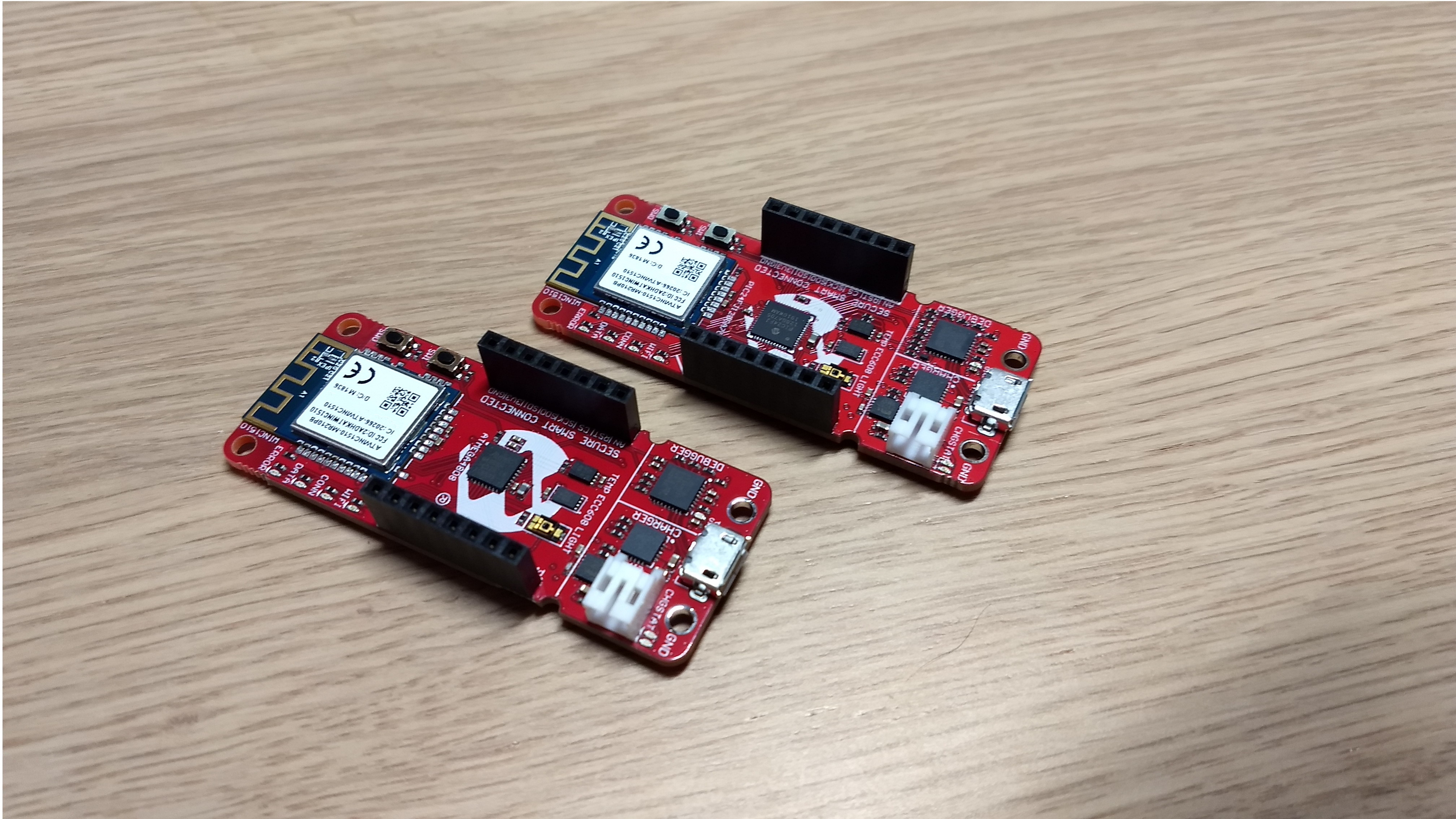
The front section (Figure 3) provides a micro-USB port to connect the system to the debugger or to provide power to the board.
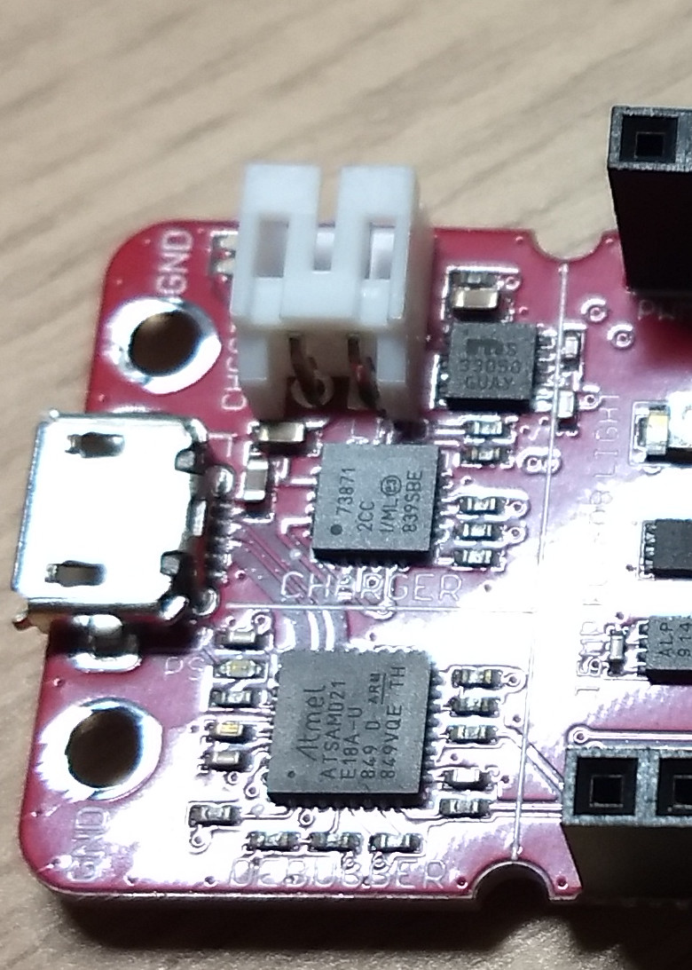
Beside the USB connector you can see the debugger, and above it is a lithium battery charging circuit. With the appropriate battery, this means we can use the board as wireless standalone device.
Hardware for the evaluation boards
The power section features an MCP73871 Li-Ion/LiPo charging IC with power path capabilities supported by an MIC33050 buck converter with integrated inductor. This set of ICs itself is a nice combination, as it provides charging capabilities of a lithium cell with 4.2 V cell voltage (be careful to use suitable cells) and a DC/DC converter that can deliver up to 600 mA current.
Also, note that the charging IC’s power path works as an ideal diode, preventing current flow from the battery back to the USB port. But this is just the power supply. There is more on the board that deserves a closer look. Moving a bit to the left, we can see two ICs and a light sensor. One is an MCP9808 temperature sensor and the other is an ATECC608A cryptographic co-processor. The latter can be used here for securing communications between this device and the AWS IoT Core services. The ATECC608A cryptographic co-processor is not limited to the AWS IoT Core but can be used to secure communications to with various cloud based services.
In the center you will find the microcontroller of choice, depending on the variant. The PIC24FJ128GA705 offers in this variant 128 KB of ECC Flash and 16 KB of RAM. Running at 32 MHz, this chip can achieve 16 MIPS and is offering a nice set of peripherals while also providing low power mode to minimize energy consumption. For the ATmega4808, being one of the newer members of the AVR family of chips, this one provides 48 KB of Flash and 6 KB of RAM. For the peripherals present, this one is more an XMEGA chip than a classic AVR one. The ATmega can be clocked up to 20 MHz and offering 20 MIPS with an enhanced set of peripherals and options to save power.
Finally (Figure 4) further left we can find the ATWIN1510 Wi-Fi module, enabling network communication.
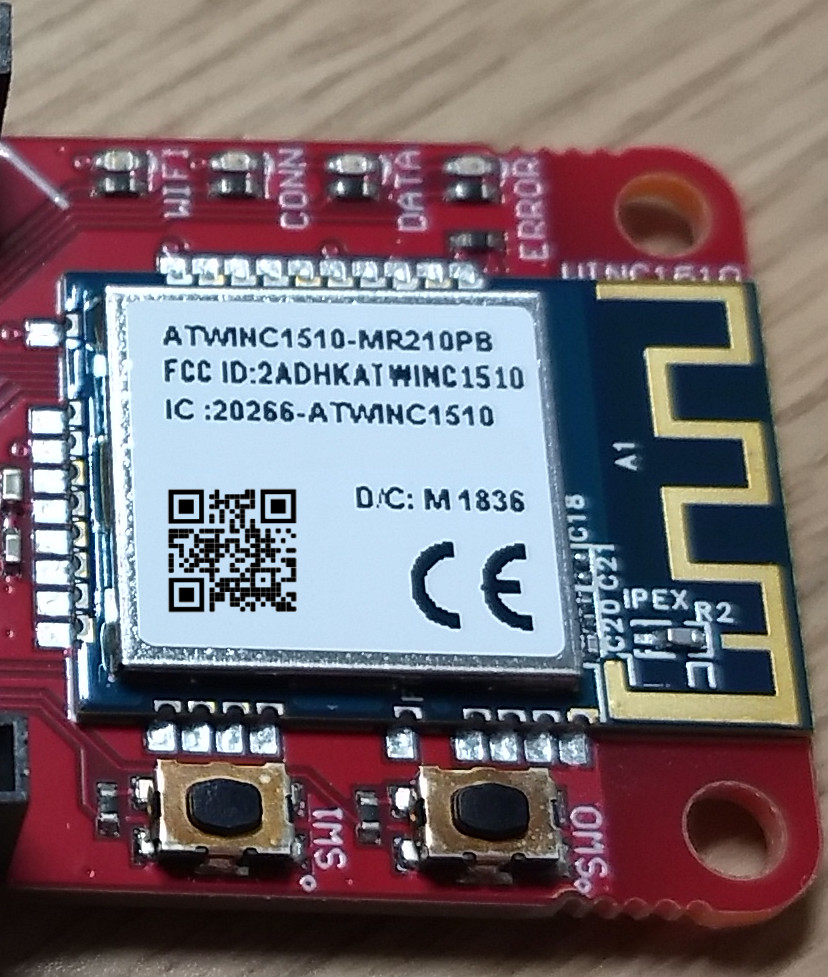
It supports IEEE 802.11 b/g/n network access as single band 2.4 GHz network controller that can be accessed through SPI. The ATWINC1510 is more than just a Wi-FI network card; you can consider it to be a network coprocessor that can lift the heavy task of traffic encryption and TCP/IP packet handling from your MCU inside the ATWIN1510.
The connector at both sides (Figure 5) are microBus Click board connectors that allow you to add additional sensors and devices to the board from the range or microBus compatible devices, like 3D Motion detection.
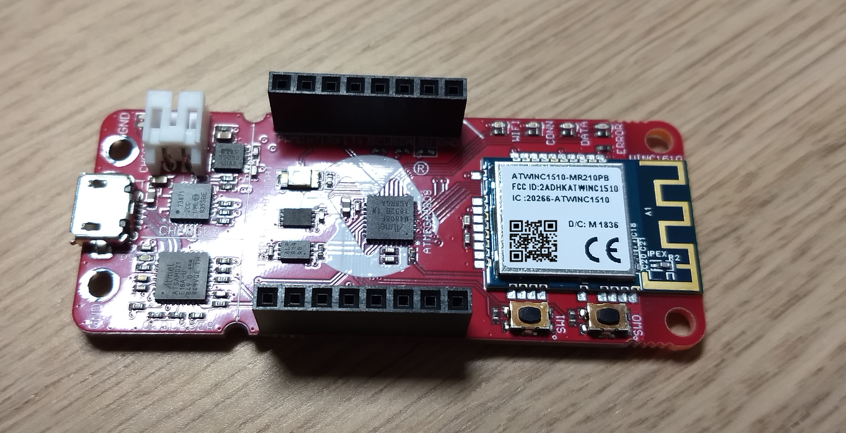
For the pins and functions on the board it is enough to just flip it. The available connections are marked with their name and pin as shown by Figure 6.
For those that are interested in more details for the boards, like schematics, Microchip will provide nice crafted starting guides for both boards, not only telling you what is on those boards but also give you schematics and a quick-start guide on how to connect with them to AWS.
Preloaded software
For both boards, they will come with preinstalled sample applications allowing a direct out-of-the-box test for the AWS IoT Core utilizing a Microchip account. At this point a word of warning, which is also to be found in the quick-start guide. Data sent to this account will be available to all that have the credentials, meaning in this case that it can be considered public. Integrating this device into your existing networks is a straightforward task. Connect the board of your choice to your computer and a new mass storage drive called CURIOSITY will appear. In the root directory it contains a CLICK-ME.HTM file that can be opened in a browser and guide you through the configuration steps. First, we need to upgrade the firmware to the latest version; otherwise, we will get into trouble configuring the Wi-Fi network. As you can see in Figure 7, you will be guided first to download the latest firmware for your board.
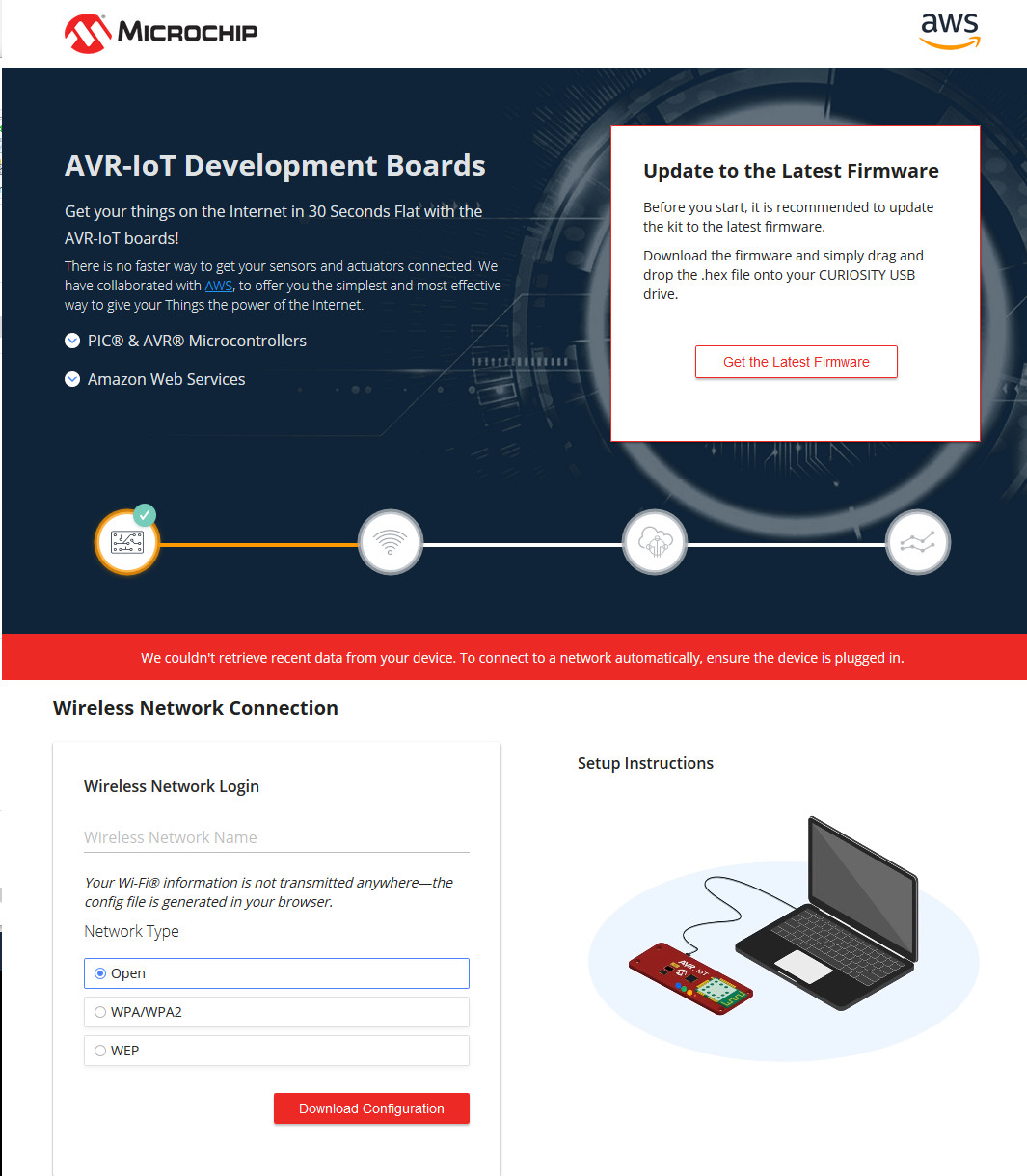
This update will bring the MCU to the latest released firmware. As the onboard security chip will not be updated by the MCU firmware, it may contain outdated firmware or certificate information. If you have trouble connecting your board to the AWS IoT core have a look at the textbox “Something not yet in the manual,” as this will update all components on the board to the latest version. For the update, drag the downloaded .hex file to the drive. After you drag and drop the file on the CURIOSITY drive, the new firmware will be flashed and the MCU will reboot.
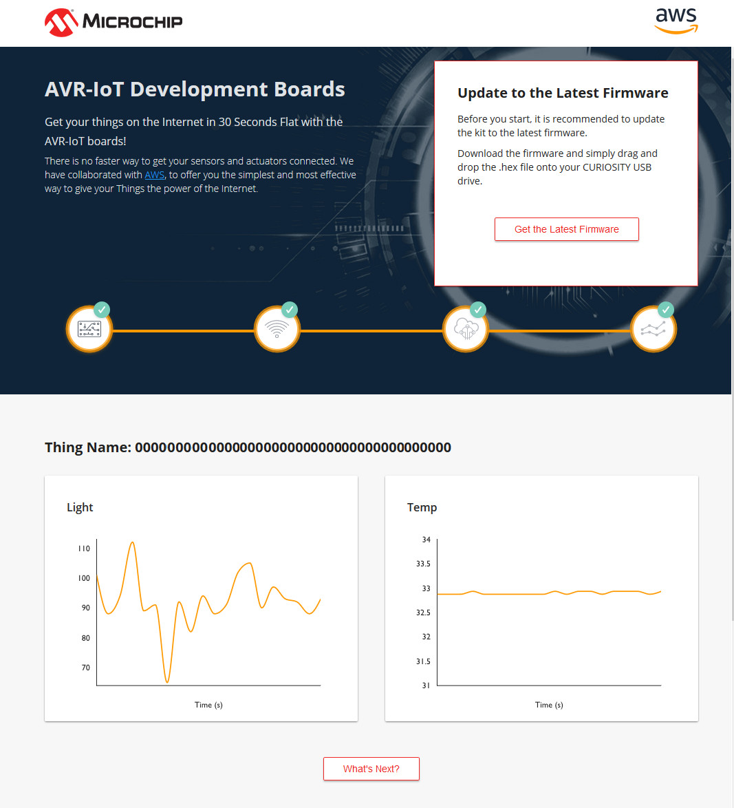
Getting the device into your Wi-Fi network is also just a matter of a few clicks.The CLICK-ME.HTM in the root of our CURIOSITY drive allows you to enter your Wi-Fi credentials and will generate a WIFI.CFG file for you. This generated WIFI. CFG you can drag and drop onto the CURIOSITY drive to store the Wi-Fi credentials inside the MCU and establish a Wi-Fi connection to your network. If the connection to your network is established the device will try to connect to the AWS service and start publishing data. With the opened CLICK-ME.HTM this will look like Figure 8.
What’s next?
The little button below our sensor values will guide us through the next steps — the first of whihc is setting up MPLABX (Figure 9).
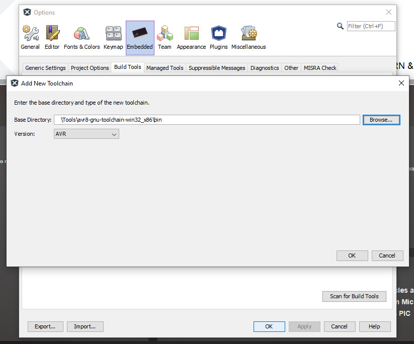
After the Microchip-Atmel merger, the MPLABX development environment, formally dedicated to PIC development, added AVR and SAM device support. While you do not have the look and feel of an Atmel Studio (a Visual Studio-based environment), you will love the fact that you are no longer bound to Windows. Users of Mac OS and Linux will also be able to start AVR-based projects on their AMD64-capable machines. Those of us running only on a 32-bit-capable CPU or using a 32 bit operating system will be out of luck with the latest version of MPLABX. MPLABX is based on Netbeans, a development environment started as an IDE for Java and over time extended to other languages and was later adapted by Microchip to become MPLABX. At the time I write this article, version 5.45 is the current release and will be used on a Windows machine for this review. For the different architectures, we need to install the compiler and support files. The easy way doing this is during installation, and if there is enough space on the drive, just choose all supported architectures to get the support files. For the compiler we will be informed at the end of the setup that we need to fetch them from the Microchip site. For those who want to use the AVR-GCC compiler (the one included usually with Atmel Studio 7), you need to download this one manually from the Microchip site, extract the .zip file and add manually the compiler to MPLABX. Adding the compiler to MPLABX is shown in Figure 9. Choose the path where you extracted the compiler files. Be aware that you need to specify the ‘bin’ folder; otherwise, the AVR8 toolchain is not recognized. The sample projects will compile per default with the XC compiler series, meaning this step is not required but can be convenient if you are used to the way the AVR-GCC works.
AVR-IoT WA Development Board
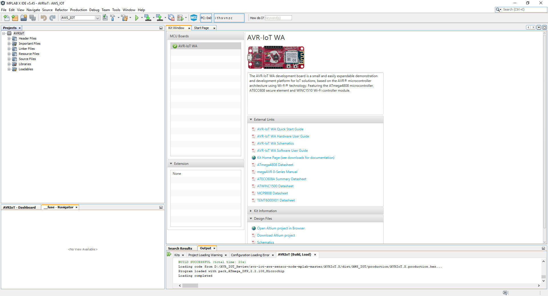
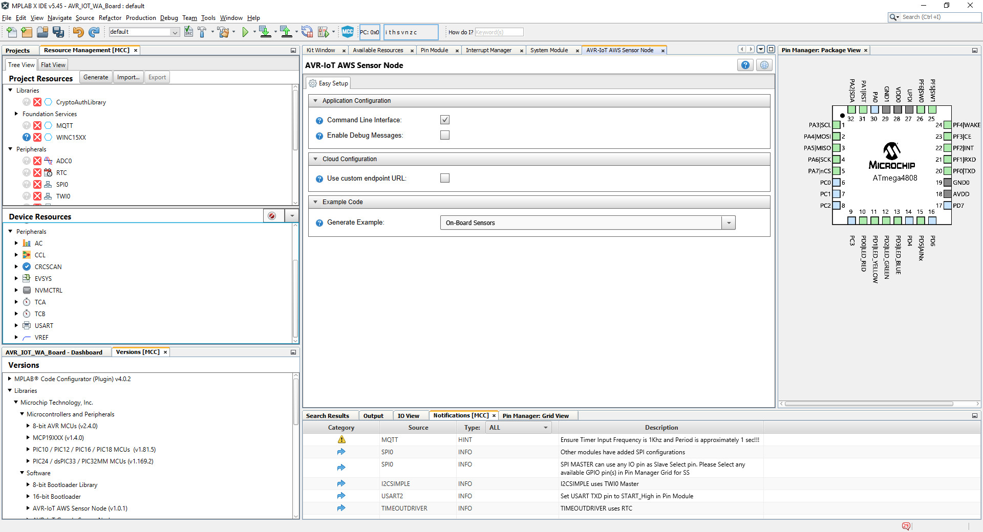
We also need to download the latest AVR-Iot WA Application. After downloading the code this can be opened with MPLABX and it will bring the project as seen in Figure 10.
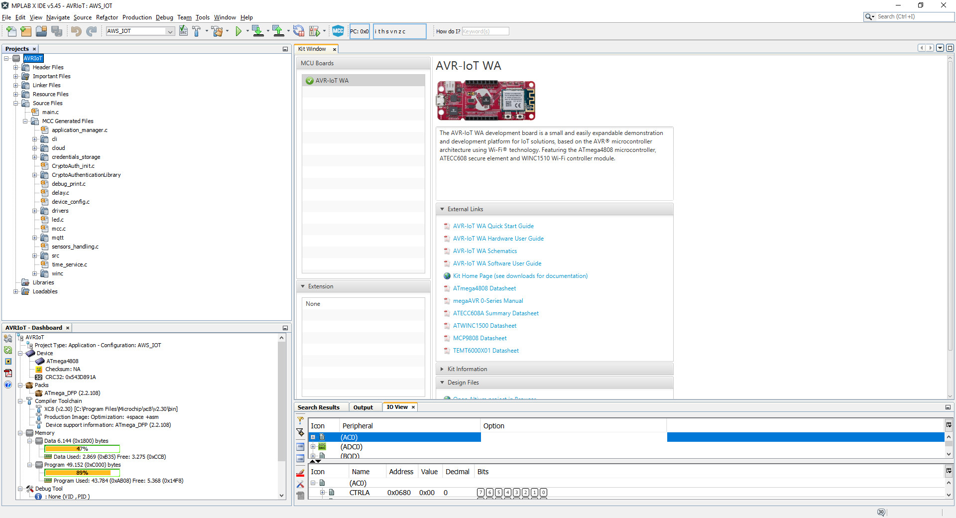
You may notice that with the connected board you also get all resources and links to documentation presented. The code is required to get the next steps for the tutorial passed and allows you to learn how you could adapt the code for your own needs or use the developed ideas and configuration to speed up your development. The opened and expanded project can be seen in Figure 11.
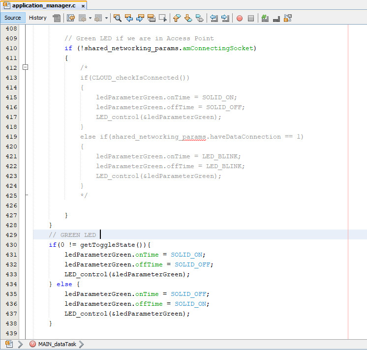
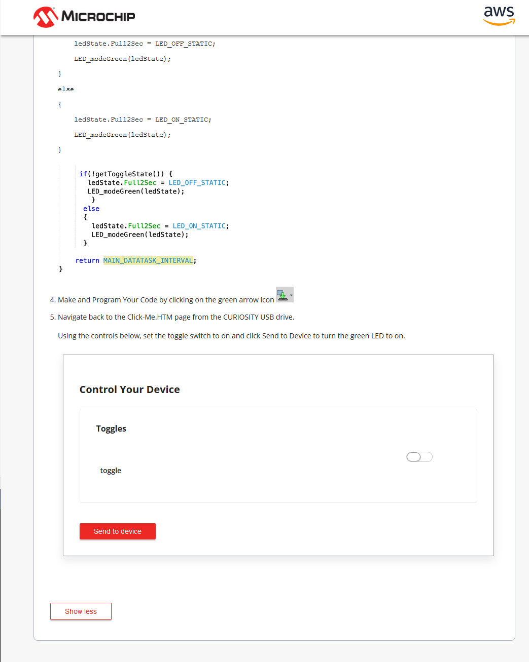
The last step of the tutorial for the AVR-IoT WA Board at the time of writing is a bit behind the structure of the actual code and requires some seconds to figure out the corresponding parts of code. To make starting a bit easier in Figure 12 the required code changes are shown to let the green LED work as an actuator.
After the changes are included in the source code, it can be uploaded to the AVR-IoT WA Board and the LED state can be controlled with the nice slider as shown in Figure 13.
Besides this little glitch in the last step of the tutorial, the board works like a charm. If you have completed the tutorial, the Microchip IoT Developer Guides for AWS offer further information and tutorials for using these boards with the Amazon Web Services.
PIC-IoT WA Development Board
Like with the AVR, the PIC-IoT WA Application must be downloaded and can be found here. The code can be opened in MPLABX and has the same structure as the one for the AVR. The tutorial works the same as with the AVR one, except that the PIC offers a lot more Flash, some advanced peripherals, and also a bit more RAM (see Figure 14).
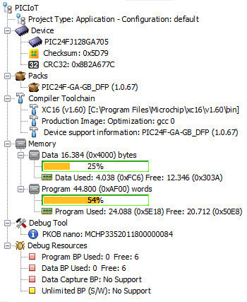
Also notice that the PIC offers more breakpoints in hardware for debugging your software and data watchpoints compared to the AVR with a less efficient instructions per clock than found on the AVR. If you want to explore a bit more of the provided code, you someone will likely wonder about the main.c as the code is really short as the following listing shows.
#include "mcc_generated_files/application_manager.h"
int main(void)
{
application_init();
while (1)
{
runScheduler();
}
return 0;
}
The initialisation of all components is handled inside application_init() . This function can be found inside the application_manager.c where most of the high level functions can be found. The code uses the runScheduler() function to serve all tasks that need to be done and coordinate them in a timely manner. From runScheduler() we have a function called timeout_callNextCallback() that actually will execute tasks that are due and is shown in the following listing.
inline void timeout_callNextCallback(void)
{
if (executeQueueHead == NULL)
return;
bool tempIE = (IEC0bits.T1IE == 1?1:0);
IEC0bits.T1IE = 0;
timerStruct_t *callBackTimer = executeQueueHead;
// Done, remove from list
executeQueueHead = executeQueueHead->next;
// Mark the timer as not in use
callBackTimer->next = NULL;
if(tempIE)
{
IEC0bits.T1IE = 1;
}
uint32_t reschedule = callBackTimer->callbackPtr(callBackTimer->payload);
// Do we have to reschedule it? If yes then add delta to absolute for reschedule
if(reschedule)
{
timeout_create(callBackTimer, reschedule);
}
}
The code will probe if anything is ready to be executed, and if not, it will return immediately. In the following the code will first disable for a short time a timer interrupt, why we will discuss later, and grab the element that is ready to be execute and call the function. The call uint32_t reschedule = callBackTimer->callbackPtr(callBackTimer->payload); is executing the function and the function itself returns the timespan when it will be needed to be called again. If this timespan is greater than zero, it will be put back in a list of waiting tasks with the given timespan. The timer and timer interrupt mentioned is the other part that keeps the system executing tasks. At a defined interval the function timeout_isr is called from within the timer interrupt.
void timeout_isr(void)
{
timerStruct_t *next = listHead->next;
absoluteTimeofLastTimeout = listHead->absoluteTime;
lastTimerLoad = 0;
if (listHead != &dummy) {
enqueueCallback(listHead);
}
listHead = next;
startTimerAtHead();
}
Simplified the code checks a list of tasks. Inside this list can be tasks that needs to executed or dummy tasks that will do nothing. If a task needs to be executed, it will be put in a list of tasks that are due. The next task from the list of tasks that are waiting to be executed will be grabbed and the timer will adjust its interval accordingly. The list with the due tasks will be handled by the timeout_callNextCallback function we have looked at. The isr is actually preparing and scheduling tasks that need to run next, driven by a timer. Combined with the timeout_callNextCallback function this generates a cycle where tasks are managed end executed in a timely manner. If no tasks need to be executed any longer the MCU could be put to sleep and wait for the next time it is woken up by the timer or another event. This nice concept is not only suited for this case of operation but it might also be interesting for other projects to run tasks with reduced power consumption.
One step further
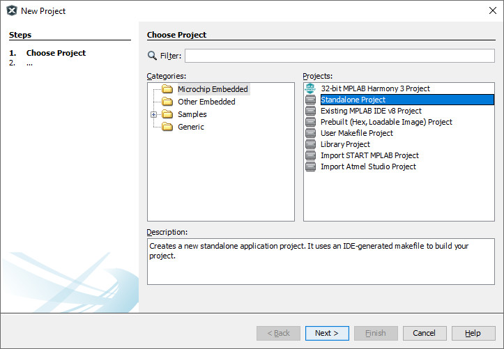
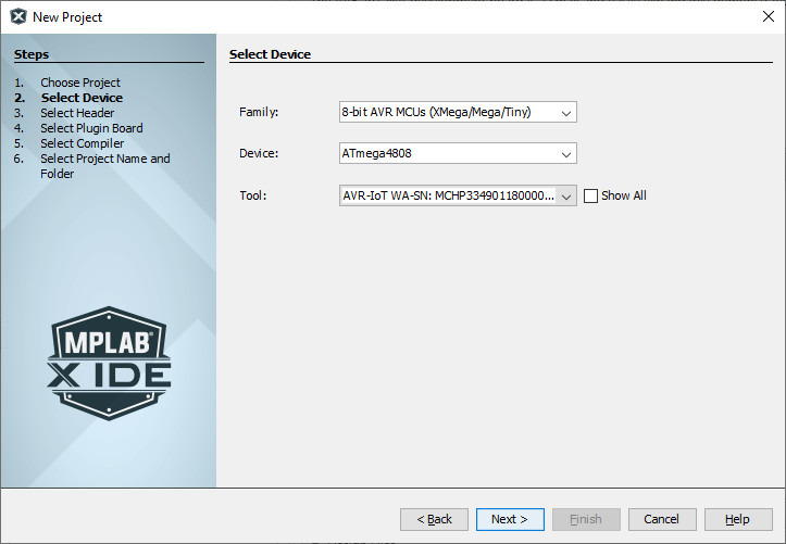
For the AVR-IoT WA Board, you find a guide to start the sample project from scratch moving through MPLABX. This gets you more familiar with the development environment and the code generation itself. A word of warning, even if this is supported and working, some parts and plugins will undergo enhancements to even increase user experience and stability. Figure 15, Figure 16 and Figure 17 show a few steps on your way through the wizards.
After the steps from the user guide are done, you will have a project that can also be compiled with the AVR-GCC if you need to include code written for that specific compiler.
You also see in Figure 17 the components included with the AWS IoT Core Sample project, like the CryptoAuthLibrary, WINC15XX or Message Queue Telemetry Transport (MQTT). This leads to the security aspect of both evaluation boards. The AWS IoT Core uses MQTT for data exchange. If no additional measurements are taken, data is exchanged in plain text, so data can be modified on the way from the device or back, something not wanted. Therefor MQTT can use Transport Layer Security (TLS) to encrypt communication. On both boards, the ATECC608A is installed and used as cryptographic co-processor offloading work from the MCU and acting as secure element to your devices. For network security, the WINC1510 offers TLS encrypted communication and can be assisted by the ATECC608A to ensure that the data passed between the evaluation board and the remote side cannot be changed. With MQTT used by the AWS IoT Core, this also means we are not limited to the AWS IoT Core. We just need an MQTT broker that will accept our connections and processes data.
Easy entry with AVR-IoT and PIC-IoT boards
With the given price point and software support both the boards offer, there is nothing to worry about. Combined with the well-equipped documentation and debugging facilities, the boards offer an easy entry into connected devices that run on restricted power. The included lithium battery circuit offers flexibility beyond just the workbench, and the microBus connector gives you instant access to a lot of additional hardware for your projects. You can stay with your preferred MCU architecture with these boards, or you can use the chance to get used to the other side and experience what these will offer you. In combination with the onboard debugger, provided on both boards and a cross platform solution for all three major operating systems, this is a more than complete solution.
Something not yet in the manual
It is possible that the board that ships to you is preloaded with older firmware and the data on the ATECC608A may be outdated. As a result, the board will connect to your WiFi network just fine, but it will be unable to connect to the AWS IoT Core, which means you will not be able to process the tutorials or other steps any further. To get the board up to the latest firmware, including the ATECC608A and the onboard debugger, you can use the IoT Provisioning Tool. This one runs on all three major operating systems as command line application. Unpack the downloaded file, use a command line (Windows user can use cmd.exe for it). For Windows, the command will be iotprovision-bin.exe -c aws -m sandbox. After this is done your board and all required certificates are in place. As sidenote, if you prefer the Google services have a look at Microchip’s video tutorial on how to switch cloud provider.
Discussion (0 comments)