
Review: ATtiny817 Xplained Mini
Programming the ATtiny817,
meaning writing an executable into the chip’s program memory, is done over a so-called Unified Program and Debug Interface or UPDI. This sounds like the PDI of the ATXmega processors, but it is not the same. UPDI is also different from TPI used on tiny AVRtinies like the ATtiny4. Like PDI, UPDI supports debugging but only uses one wire; like TPI a 12-volts pulse applied to the reset pin enables UPDI mode (it can also be activated by programming a fuse). The six-pin connector compatible with all three interfaces remains.Before adopting the ATtiny817 and its family members make sure you have the right tool to program them.
Atmel Studio 7 (AS7) knows the ATtiny817 Xplained Mini board
When you launch AS7 and then connect the board to your computer the IDE will detect it and open a page for it with links to documentation. You can also click New ASF Example Project but the windows that opens doesn’t have any. Clicking Update Kit Information didn’t improve things, but it created a new link to the Atmel Start website. Clicking Kit Userguide brought up a 404 Not Found page.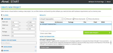
Following the Atmel Start link takes you to an interface where you can configure a project in a way similar to the ASF wizard in AS7, but online. You can select a board and the drivers for it, play with the port multiplexer and the event system, configure middleware libraries, and, when you’re ready, you can download (export) the project to your computer and import it in AS7, IAR Embedded Workbench or as stand-alone with makefile. You can export all three in one ‘pack’. The file you download has as extension ATZIP, but you can rename it to ZIP and unpack it any way you like.
I configured a project to control the user LED on PC0, read the user button on PC5, and do something with the QTouch buttons on PA6 and PA7. First I added the drivers for what I wanted: the PTC touch controller, a USART because that is always useful, and the Event System to see if I could do something with it. The wizard creates a block diagram for this, but it did not show the PTC. Also in the code preview no traces of the PTC except in the documentation part where it lists an empty file. Going through the Add Component step once more I found a QTouch Library in the Middleware section. Adding that resulted in a new tab QTouch Configurator. Now I could create buttons and connect them to PA6 and PA7 (make sure they are free in the PINMUX Configurator). Still no trace of PTC, so let’s assume that this is normal. In the PINMUX Configurator I created labels for led0 and user_button. In the Event System Configurator I connected PC5 to channel 2 (only possibility) and then to Event Output 0 (options possible: 0, 1 & 2).

I then downloaded my configuration for possible later use and subsequently exported it as project for Atmel Studio.
Read full article
Hide full article
Discussion (3 comments)