If your microcontroller is missing a feature, you’ll likely find a device featuring either SPI or I²C to extend its functionality. Whether you are short of flash or SRAM memory, want to measure temperature, or even wish to implement a digital potentiometer, there is a solution out there.
If your microcontroller is missing a feature, you’ll likely find a device featuring either SPI or I²C to extend its functionality. Whether you are short of flash or SRAM memory, want to measure temperature, or even wish to implement a digital potentiometer, there is a solution out there. However, if you have the luxury of choosing between SPI or I²C, how do you decide?
Both interfaces came to prominence in the 1980s, developed to support communication between integrated circuits (IC) at board level; in fact, I²C is short for Inter-Integrated Circuit. They are also synchronous interfaces, meaning that one of the devices supplies a clock. This ensures that everyone agrees at what moment in time each bit of data being transferred is valid.
Unlike serial interfaces such as RS-485 or CAN that handle long-distance communication, neither I²C nor SPI requires a transceiver. Thus, they are quite simple for chip designers to integrate into both microcontrollers and the myriad of peripherals they connect to.
What is I²C?
Defined by Philips Semiconductors (now known as NXP), I²C is a half-duplex communication standard. It uses just two pins: a clock line known as the serial clock line (SCL) and a bi-directional data line known as the serial data line (SDA ). A basic system usually consists of a microcontroller acting as a master connected to multiple slave devices, something that has been covered here.
This means that devices designed to communicate over this interface need as few as four pins: SDA, SCL, power, and ground. Some devices are implemented in tiny packaging barely bigger than the die itself. This raises some questions: How does a slave know if it is being spoken to? And should it be receiving or sending data?
How many devices can I²C support?
Most I²C devices have a 7-bit address. The master sends the address over the bus along with an eighth bit that indicates whether this message is a read or write request. A write request is followed by one or more bytes of data. Slave devices respond with one or more bytes of data upon the reception of a read request.
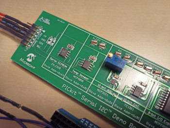
MCP9800 I²C temperature sensor
One of the challenges with I²C can be the addressing. Many slave devices are programmed with a fixed address. If you want to connect four temperature sensors around a board, they can’t all use the same address. Some peripherals get around this by providing extra pins that, through pull-ups and pull-downs, allow the selection of one address from a small range. For example, the 8-pin Microchip MCP9800 temperature sensor offers addresses from 0x48 to 0x4F.
Even with a 7-bit address range it is still not possible to connect 127 devices to an I²C master. Due to its design, the specification limits the total capacitance on the bus to 400 pF. This supports about 20 devices in total.
How fast is I²C?
I²C devices typically operate with clock frequencies of 100 or 400 kHz. Extensions to the specification have pushed this up to 5 MHz more recently. By today’s standards, even these higher speeds are not especially fast and the actual throughput of data is quite a bit slower. Because the device selection and read/write control operates in-band (control data is sent in the same channel as the data), this takes away some of the available bandwidth.
The protocol also requires a start and stop bit that top and tail each message. Additionally, each byte of data has to be acknowledged with either an ACK or NACK. This results in nine clock pulses being needed for each byte of data transferred.
How do I calculate I²C pull-up resistor values?
Unlike typical microcontroller input/output pins, I2C pins use an open collector design. This means pull-up resistors are needed to pull the signal up to the supply voltage. Without the pull-up, the bus doesn’t work. A common question is: how do I calculate the correct resistor value?
The I²C specification (chapter 7) provides two equations that give upper and lower limit values. The upper limit value depends on the maximum allowable signal rise time (1000 ns at 100 kHz, 300 ns at 400 kHz) and the total capacitance on the bus. The lower limit depends on the supply voltage, the upper output-low voltage (typically 0.4 V), and the output-low current (typically 3 mA). Thus, for a 5 V system using a 100 kHz clock and a 50 pF bus load, the pull-up resistor can lie between 23.6 kΩ and 1.5 kΩ.
where VOL(max) is 0.4 V and IOL is 3 mA for both 100 kHz and 400 kHz operation.
Figure 1: The I²C specification provides equations for calculating the upper and lower allowable pull-up resistor values.
What is SPI?
SPI, or the Serial Peripheral Interface to give it its full name, was developed by Motorola and has been covered previously here. It uses three pins: a serial clock, SCLK, generated by the master device, and then two unidirectional data lines. One, MOSI (Master Out Slave In) sends data from the master to the slaves. The the other, MISO (Master In Slave Out) receives data from the slaves to the master. This allows a slave device to return data at the same time as it receives data from the master.
How many devices does SPI support?
TC77 temperature sensor using SPI
When more than one slave device is in use, an out-of-band device selection mechanism is implemented to choose the correct one. A slave select, or SS signal, that is active low is required for each SPI device connected to the microcontroller. This means that a microcontroller needs 3 + N pins to support SPI, where N is the number of slaves connected to it. As a result, SPI needs more microcontroller pins than I²C.
How fast is SPI and where is the specification?
The SPI interface was never standardized, so there are lots of variants in use. The idle state of the SCLK and whether data is valid on the clock’s rising or falling edge can make it challenging to configure. Some devices, however, often support clock speeds of many megahertz. This, coupled with the efficient full-duplex communication protocol, means that it is faster than I²C for the same peripheral device. This is critical when using EEPROMs for boot-strapping a microprocessor, or when supporting over-the-air (OTA) firmware updates.
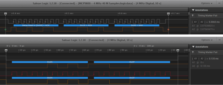
I²C (top) requires around twice as long for a 16-bit register read than SPI (bottom) for the same clock frequency.
Which should I use?
The decision of whether choose I²C over SPI is difficult as so many factors are at play. These range from data throughput and device availability to system power consumption. SPI is definitely faster. Reading a 12-bit temperature value from a sensor is almost twice as fast as I²C for the same clock frequency (see above). SPI also allows you to just read 12 bits rather than forcing you to complete two 8-bit reads as with I²C. However, if your microcontroller is pin-limited and the sub-MHz clock speed is fast enough for the application, a bus of I²C slave devices will be easier to accommodate in your circuit.

Discussion (0 comments)