Need a compact solar power regulation module for low-consumption systems? This solar cell voltage regulator is designed to sit between a solar panel and a rechargeable battery. The circuit ensures efficient charging, protects against over-discharge, and enables monitoring.
Need a compact solar power regulation module for low-consumption systems such as weather stations or outdoor LED lighting controlled by a timer? This 2016 solar cell voltage regulator project is designed to sit between a solar panel and a rechargeable battery. The circuit ensures efficient charging, protects against over-discharge, and allows monitoring through a USB/serial interface. The regulator supports solar panels in the 10–50 W range and can easily be adapted for higher power systems.
Circuit Design and Operation
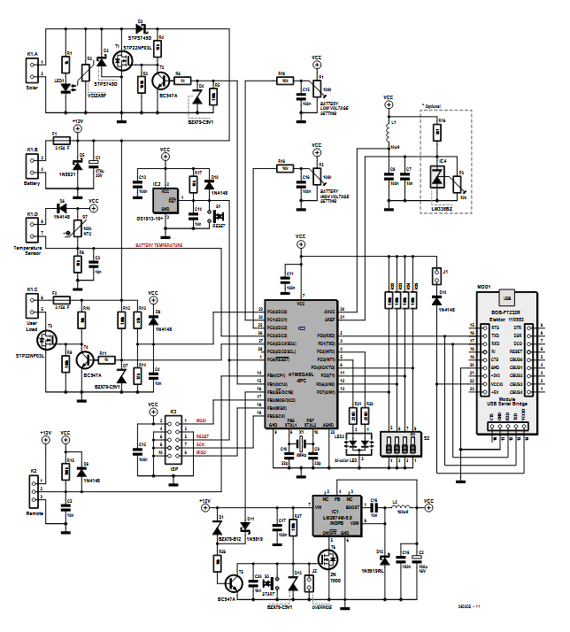
At the heart of the solar cell voltage regulator system is an ATmega8 microcontroller clocked at 4 MHz. The design uses a switch-mode step-down regulator (LM2674) from Texas Instruments, chosen for its high efficiency and low dissipation compared to linear regulators. This allows the regulator to operate effectively even with a 24 V supply, maintaining minimal power loss.
Solar cell regulator schematic. The components within the dotted line are not used (omitted in this version).
The battery voltage enters via connector K1.B, protected by fuse F1 and diode D5 to prevent reverse polarity. The LM2674 switching regulator (IC1) is driven through transistor T5 and MOSFET T6, providing stable regulated output voltage to the system while efficiently managing power from the solar input.
Voltage monitoring is handled by the ATmega8’s ADC channels:
ADC0 measures the battery voltage through a divider and filter network (R13, R14, C4).
ADC1 and ADC2 read adjustable potentiometers (P1 and P2) used to manually set high and low battery voltage thresholds.
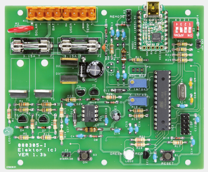
Solar cell voltage regulator PCB
"The dimensions of the circuit (excluding the battery) correspond to those of a Fibox watertight case," notes Pascal Rondane, the designer. "The cable outputs pass via cable glands (PG9). Two 2 mm holes must be drilled in the bottom of the case to drain off any condensation."
Firmware
The microcontroller’s firmware ensures intelligent power management. If the battery voltage drops below a preset threshold, the system disconnects the load to prevent deep discharge. Once the battery voltage recovers above the high threshold, the system automatically reconnects the electronics. The software also accounts for the battery type (lead-acid or gel) to optimize charge cycles and minimize memory effects.
The microcontroller-driven solar cell regulator is designed for a 12 V solar panel and a power of 10–50 W.
The Original 50-W Solar Cell Voltage Regulator Project
The original article, “50-W Solar Cell Voltage Regulator,’” appeared in Elektor May/June 2016. You can read the article for free during the two-week period following the publication of this post. If you create a circuit of your own, please share it on the Elektor Labs platform!
Editor's Note: This article first appeared in a 2016 edition of Elektor. Given the project’s age, some components or products might not be available, and the key design techniques might seem antiquated. However, we believe the circuit will inspire you to start new projects in the future.
Subscribe
Tag alert: Subscribe to the tag Power & Energy and you will receive an e-mail as soon as a new item about it is published on our website!


Discussion (0 comments)