Tired of loud TV ads? In 2012, Peter de Bruijn built the Mini-Mute — a clever circuit that let him mute his TV with a simple tap on the coffee table. Here's how it works.
Back in 2012, Peter de Bruijn was tired of fumbling for the remote every time a TV commercial suddenly blasted through his living room. So, he designed the Mini-Mute. With it, he could just tap his coffee table to instantly mute the sound. Let's take a look at the compact, PIC microcontroller-based circuit.
Mini-Mute Circuit
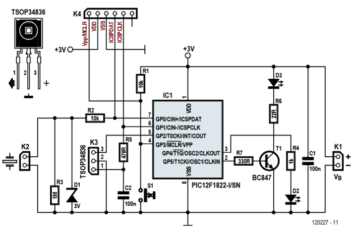
The Microchip Technology PIC12F1822-based circuit can sense vibration from a knock and send an IR signal to silence a TV. No remote required! When the program resumes, another tap can bring the audio back.
In addition to the 8-pin PIC microcontroller, the design uses a piezoelectric transducer connected to the GP0 input for signal detection. A Zener diode (D1) protects the input from overvoltage, while the GP5 output controls an IR LED via transistor T1 to transmit infrared mute commands to a TV.
The PIC12F1822-based circuit Mini-Mute circuit.
"Pushbutton S1 allows the circuit to learn the right mute command," he explained. "If it is pressed and held for a while, indicator LED D2 lights up and the mute code transmitted by the original remote control unit can be read in using an IR receiver module (type TSOP34836) connected to K3. This code is stored in the PIC. Connector K4 is used for programming the PIC. The pinning is compatible with the Microchip PICkit programmer, among others."
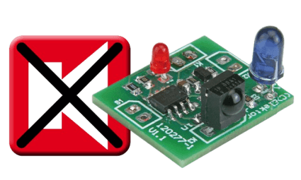
The compact Mini-Mute.
PCB and Enclosure
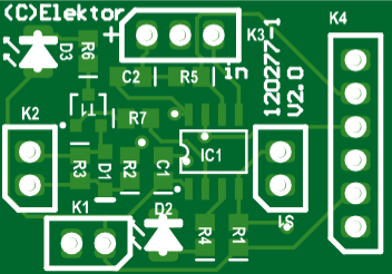
The compact PCB layout relies mostly on SMD components. De Bruijin proved that the circuit board and a pair of 1.5-V cells could easily fit in a compact box 5 × 2.5 × 7 cm box. A smaller box can be used with a button cell. Power is supplied by a 3-V button cell or two 1.5-V batteries, with the circuit drawing under 100 nA in its ultra-low-power sleep mode, eliminating the need for a power switch.
The compact PCB
The Original Project
The original “Mini-Mute” article appeared in Elektor 7/8-2012. You can freely access this DIY electronics article during the two-week period following the publication of this news item. If you start an interesting project of your own, please share your progress on the Elektor Labs platform!
Editor's Note: This article originally appeared in a 2012 edition of ElektorMag. Some components or products may no longer be available. However, we believe the project will inspire you to start new electronics projects of your own.
Subscribe
Tag alert: Subscribe to the tag Circuits & Circuit Design and you will receive an e-mail as soon as a new item about it is published on our website!


Discussion (0 comments)