Regardless of whether you love it or hate microcontroller documentation, you still have to negotiate it. In the first part of this article series, we looked at what is found in a microcontroller datasheet. Here we go deeper and look at how users are informed about the device's functionality, covering everything from registers to peripheral block diagrams.
Regardless of whether you love it or hate microcontroller documentation, you still have to negotiate it. In the first part of this article series, we looked at what is found in a microcontroller datasheet. Here we go deeper and look at how users are informed about the device's functionality, covering everything from registers to peripheral block diagrams.
Datasheet: first pages
Now that you know what is included in a datasheet, it is time to start looking at some of the details. Datasheets seem to have a rather odd way of describing things, and different suppliers create their descriptions and drawings in different ways. Microchip Technology's 8-bit PIC16F18877 microcontroller remains our focus, and you should download the datasheet if you want to follow along.
Upon downloading and opening the datasheet, the first two pages to confront us provide a brief description of this microcontroller along with a list of the main features and the peripherals included. "Core features" are not stand-alone peripherals; these are capabilities that are closely linked to the processing core. These cover capabilities such as brown-out circuitry, which detects when the supply voltage drops below the required level, and watchdog timers, which reset the microcontroller and are often used in safety-critical systems.
Subscribe
Tag alert: Subscribe to the tag microcontrollers and you will receive an e-mail as soon as a new item about it is published on our website!
The third page puts a little more meat on the bone, explaining how many of each peripheral we get, and how much RAM, program flash, and EEPROM is implemented. This is complemented by pages four to seven that provide basic packaging information and explain which functionality is assigned to which pin.
The "Pin Allocation Tables" are a critical element of any microcontroller datasheet. With so much capability being packed into each die, microcontrollers today have more functionality than they have pins. Thus, one of several capabilities (and sometimes more than one) can be assigned to each pin. On this device, we can see that pin "RA2" can be used as an ADC input, an analog voltage reference, a comparator input, a digital-to-analog converter (DAC) output, or as an interrupt-on-change pin. In order to provide some flexibility, you may also find that a specific capability can be switched between one or more pins. The assignment of functionality to pins can be, as a result, very complex.
Understanding register descriptions
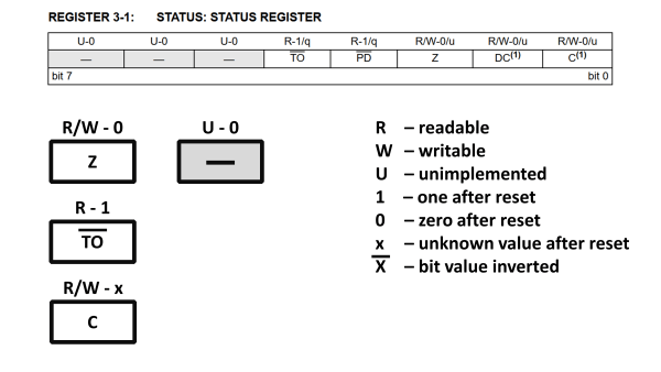
Register descriptions are composed of two parts: the name of the register and the names of the bits (or groups of bits) within the register. Page 38 of this datasheet describes the functionality of the STATUS register, which is part of the processor. This register is composed of bits that are implemented, and some that are "not implemented."
Bit descriptions of registers can seem a little cryptic.
(Source: Microchip Technology)
The implemented bits are marked with a combination of "R" and/or "W" to indicate whether they can be read or written. After the hyphen typically comes a number: "0" or "1." These indicate the value of this bit after the device has been reset. Some bit may be marked with an "x," indicating that the value will be unknown. The value of some bits may depend on what caused the microcontroller to come out of reset. If the microcontroller was simply powered-up, it awoke through a power-on reset (POR). If the power supply caused a brown-out reset (BOR), this may also result in a different value in a specific bit. In this example, such "reset-dependent" bits are marked with "q."
Unimplemented bits can be a little dangerous. According to this datasheet, reading the upper three bits should read a "0." It is unclear, however, what happens if you were to write to these bits. The datasheet may provide a general recommendation. If none is provided, you should probably ensure that any writes to such registers ensure unimplemented bits are cleared to zero. In C/C++, this can be done as follows:
myValue &= 0b00011111; // clear 3 most-significant bits (unimplemented bits)
STATUS = myValue; // write ‘myValue’ into STATUS register
Note: it makes sense to provide a comment to explain why this is being done to ensure that no-one tries to "optimize" your caution away at a later date!
The bar over a bit name indicates its value is inverted. This is the case for the "Time Out" bit "TO." When a time out occurs, which you might expect to be flagged with a positive response of "1," the response you are looking for is actually going to be "0." Often such negated bits make little sense to the programmer; you just have to live with them and treat them appropriately in your code.
Sometimes a group of bits is required to configure something, such as the prescaler for a clock source, or the baud rate for a serial interface. Such groups of bits are then named BIT_GROUP<X:Y>, where X names the most significant bit, and Y the least significant bit in the group. Also, beware: sometimes one or more bits belonging to the same group may be split across different regions in the same register, or even across more than one register!
Subscribe
Tag alert: Subscribe to the tag microcontrollers and you will receive an e-mail as soon as a new item about it is published on our website!
Time to deal with the clock
The most important part of the microcontroller is its clock peripheral. This decides what will be used as the clock source for the processor and the on-chip peripherals. It makes sense to take time to review its structure, as found on page 110. Normally, this peripheral is configured once at the start of the application's code and is never changed. If it is changed, every peripheral may be impacted, from the sampling rate of the ADC to the baud rate of the serial UART and CAN interfaces.
In this example, we have some external sources (quartz or ceramic resonator oscillators) and some internal sources. The internal sources may not be accurate enough (especially with temperature changes) to act as a reliable source for some interfaces, such as the UART. The datasheet should mention this. Otherwise, you need to check the accuracy in the section covering "Electrical Characteristics."
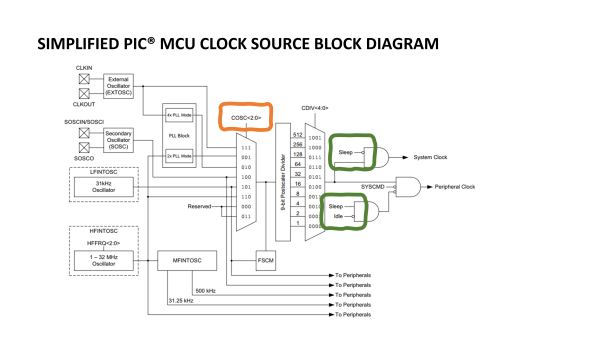
Block diagram for clock peripheral highlighting clock
selection multiplexer and controls that turn the clock
source off. (Source: Microchip Technology)
In the diagram, marked in orange, we can see that a group of three bits, COSC<2:0>, in a register most likely related to the oscillator, can be used to select between the available clock sources using a multiplexer. For reasons unknown, only the group of bits are named in such diagrams and not the register they belong to. The best way to find out which register they belong to is to search the datasheet PDF — they may be in a register of an unrelated peripheral! Multiplexer diagrams are used frequently in block diagrams where signals can be switched.
The output of this block provides the "System Clock," probably to the processor, and the "Peripheral Clock" for the peripherals. The datasheet may reference both these terms in the remainder of the document, especially when discussing any "Low Power" or "Sleep" modes. From the sections marked in green we can already infer that there is an "Idle" mode that removes the clock from the peripherals only, and a "Sleep" mode that removes the clock from the peripherals and the processor.
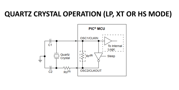
If a quartz crystal or ceramic resonator is to be used, it is likely that some guidance is provided on how to construct the circuit and lay out the PCB (printed circuit board). This is the case here too (page 112), with two capacitors being required along with an optional series resistance. The fact that four application notes on oscillator design accompany this block diagram should serve as a warning that quartz oscillators require some care in their implementation.
Recommended circuit for quartz-crystal-based oscillator.
(Source: Microchip Technology)
Beyond registers and block diagrams
Now we have covered the basics of how registers are described and how to understand the block diagram of the clock peripheral. We've even taken a cursory look at one of the oscillators and the example circuit diagram for its use together with a quartz crystal. In the next part of this series, we'll carry on by looking at another key peripheral block which needs to be well understood: the reset block. We'll also search around for all the things that the datasheet doesn't cover. If you're keen to find some resources that ease your entry into the world of microcontrollers, you may want to look at some of our introductory articles and books. Editor's note: Read the entire series on Microcontroller Documentation.
Subscribe
Tag alert: Subscribe to the tag Embedded & AI and you will receive an e-mail as soon as a new item about it is published on our website!


Discussion (0 comments)