In the previous parts of this series, we covered register functionality and took a look at the clock block diagram. Here we provide more block diagrams and investigate where you can find the rest of the required documentation.
In the previous parts of this series about microcontroller documentation, we covered register functionality and took a look at the clock block diagram. Here we provide more block diagram examples and investigate where you can find the rest of the required documentation.
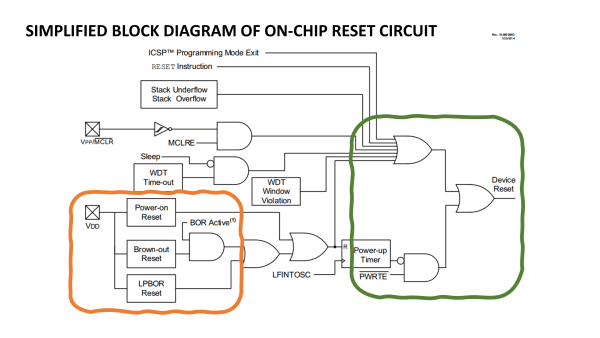
Starting again with the reset
If the clock peripheral is the most important part of a microcontroller, the implementation of the reset circuitry is the second most important block. Like the clock, it will only need configuring once (if there are any configuration options provided), but it will save a lot of trouble later if you have a good understanding of what can cause a reset.
In this example from page 100, we can see that two pins (marked as squares containing a cross, left-hand side) can generate resets. This is in addition to a range of other internal sources. One of these is the RESET instruction, two come from the stack under- and overflow, while others are linked with the "Watchdog Timer."
Marked in orange, we can see that a range of reset mechanisms, such as power-on detection and brown-out, are linked to the microcontroller’s supply pin. Here there is little control offered on this device, with essentially all interrupt sources being a potential reset signal (as marked in green). As we saw previously with the STATUS register, the cause of the previous reset can be determined in some cases.
The reset circuit provides very few configuration options, with some
reset sources being linked to the Vcc power supply pin.
(Source: Microchip Technology)
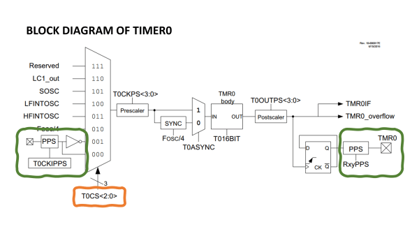
Peripheral block diagrams
The block diagrams for peripherals are as diverse as they are complex. Here we have chosen part of a simple timer (TIMER0) from page 396. Marked in orange we again see the use of a group of bits in (presumably one) register to select between a range of source inputs for this TIMER0 peripheral. Marked in green we see also that one source can be a device pin, while the block can also output a signal to a pin.
The block diagram for TIMER0 shows it has a range of clock sources,
and can even generate an output signal in addition to internal
interrupt signals. (Source: Microchip Technology)
While you may recognize the D flip-flop on the right-hand side connected to the output pin, many of the blocks in the diagram are little more than squares. Some, such as the prescaler and postscaler, are self-explanatory. The "SYNC" block seems self-explanatory but will probably require the developer to read the accompanying text in detail to fully appreciate its function. Thus, diagrams and text often go hand-in-hand in datasheets. Sometimes it is necessary to write some test code to really understand how some peripherals work.
Subscribe
Tag alert: Subscribe to the tag microcontrollers and you will receive an e-mail as soon as a new item about it is published on our website!
Building a board
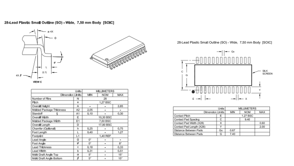
At some point, the design needs to move to a PCB if you’re planning on mass producing your design. Most computer-aided design (CAD) software will have the schematic blocks for your processor along with the "land pattern" for various packages for the PCB design. However, if they are missing, the datasheet will probably include technical drawings for each package and the associated land pattern. In this case, they can be found on page 639.
The SOIC package shown here can be found on page 645 and 646. For PCB designers, perhaps the most useful data today is the height of the package if the design is limited in volume (they will already know the width and length). Many packages today also feature an integrated "metal slug" that needs to be soldered to the PCB to aid heat dissipation. This is not the case here but, if it were, guidance on how to connect it would be given. You may also need to check whether it is connected to the ground of the device or perhaps another pin.
Package drawings provide all the dimensions of the package (left)
along with the recommended 'land pattern' for the PCB (right).
(Source: Microchip Technology)
What is only sometimes in a microcontroller datasheet?
As you will now be aware, there is a lot of information in a datasheet. However, there are a few things that may be left out because it would make the datasheet too long, or the information is common to many devices and it deserves its own documentation. These can include:
Processor instruction set – If the number of instructions is low (less than 60-70), they may all be included with an explanation in the datasheet. If not, there is probably a separate document where each instruction is explained in detail.
Code examples – These appear more often when the microcontroller is still commonly programmed in assembler. Examples in high-level languages such as C make little sense since the compiler will define the precise instructions used.
Circuit examples – These are most common in association with functionality unique to the microcontroller selected, such as the oscillator or the power supply, or slightly more complex interfaces that have specific requirements on signal loading, such as USB. However, they are more likely to be covered in more detail in an application note on the subject.
What is not included in a microcontroller datasheet?
The following items are normally excluded from the datasheet, being found instead in other documentation. This is usually because it covers a topic that is common to a wide range of microcontroller devices.
Flashing of microcontroller memory – This is normally covered separately as a topic for those focused on programming microcontrollers in mass production.
Use of development tools – The compiler, use of an Integrated Development Environment (IDE), and debug tools have their own documentation.
Detailed explanation of processor core – This will often be covered in a separate document, especially for 16-bit and 32-bit cores.
Detailed explanation of complex peripherals – USB, graphics interfaces, and Ethernet peripherals are typically covered in separate documents as the inclusion of each could double the size of the microcontroller’s datasheet.
Errata – Any errors in the documentation, or workarounds to resolve silicon bugs that won’t be fixed, are covered here.
Subscribe
Tag alert: Subscribe to the tag Embedded & AI and you will receive an e-mail as soon as a new item about it is published on our website!
What other microcontroller documentation is offered?
In addition to the datasheet, the following documents are commonly made available:
"Family Reference Manual" – While the datasheet tells you precisely what one microcontroller can do, such documents provide a higher-level overview of what all microcontrollers in a family of devices can do.
Application notes – These go into a lot more detail on how to use specific peripherals, or a group of peripherals, to implement an application or interface. The datasheet may explain how to use the CAN (controller area network) peripheral, but the application note will explain how to use it as part of a CAN network, providing guidance on higher-level software protocols, and the selection of suitable transceivers.
Programming specification – For programming in mass-production environments, this explains in detail the voltages and timings required, and any protocol used for the programming interface.
How to consume lots of written material
Unfortunately, there is no way to quickly consume all the data associated with a microcontroller and all of its tools. If you’re a beginner, it is probably best to read the datasheet alongside a book or article on the microcontroller you’re trying to use. Elektor not only has books for those interested in PIC microcontrollers; there are also starter books for the STM32 and Arm-based microcontrollers in general. Or why not try a simple MSP430 project?
The combination of practical examples coupled with two types of written explanation (a book/article and the datasheet itself) will help. If you’re more advanced, the best approach is to focus on the sections that cover the processor core, the clock tree, and the reset block, followed by the peripherals you intend to use. Then you'll need to make yourself acquainted with the documentation for the compiler tool chain. Also make liberal use of software libraries and examples to build-up your understanding, and post questions on forums if you need further help.
Datasheets can be challenging to read and understand, and aren’t the most exciting form of literature. However, they are (mostly) accurate and a technical description of functionality (the errata can be used to determine the confidence you afford the datasheet). Stick with them and, over time, you’ll develop a good understanding of how they are constructed and worded. Editor's note: Read the entire series on Microcontroller Documentation.


Discussion (0 comments)