Today, electric motors consume almost half of the electricity produced worldwide. In industry, the share is even higher, reaches about 70%. Meanwhile, major manufacturers of electronic components, such as Microchip, are constantly improving control systems for electric Actuators.
Electric Motors are everywhere - in the washing machine, dryer, refrigerator, car, fans, pumps, air conditioners etc. - making our lives easier. Therefore, it is important, that they work as efficiently as possible. The amount of energy, that the actuators consume, in no small degree is dependent on the controller, which controls the operation of the actuator. Thanks to efficient components from Microchip it is possible to make such an ergonomic system. The following shows, how such a circuit is constructed, as well as the specifications of the branded components used to make it.
BLDC Motors and their applications
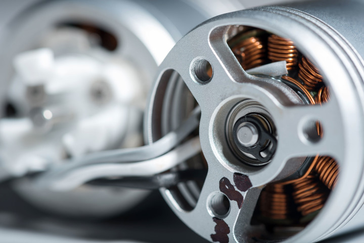
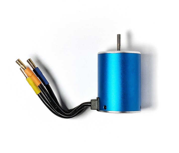
Brushless DC Motors (BLDC Motors), from Brushless Direct Current) are increasingly being selected as the motor of choice for drive applications. Brushless Direct Current) are increasingly being chosen by designers and builders to serve as Actuators. This is due to several reasons: they are characterized by high reliability, efficiency and favorable power-to-size ratio. As the name suggests, it does not use brushes - instead, permanent magnets are placed in the rotor, and the windings are located in the stator. Currents (of the desired frequency) induce an electromagnetic field and cause the magnets to repel and attract them, setting the axis of the actuator in motion and controlling its speed. Such commutation requires the use of a suitable controller, and a range of Microchip products can be used in its design, products can be used to ensure, precise and efficient operation of the entire device. Windings of a model BLDC motor.
Microchip has the advantage, that it manufactures a wide range of Semiconductors and analog circuits, and, therefore, all the most important controller components can be compiled from its offerings. These include microcontrollers, analog circuits (operational amplifiers), fPGAs, power components (e.g. transistors). From the Microchip range available through TME, you can select, for example. dsPIC® microcontrollers, PIC® and AVR® microcontrollers with integrated motor control functionality: PWM generator, a/D converter (ADC) and popular communication interfaces (SPI, CAN, UART). It is also worth noting here, that the manufacturer also provides specialized software and development tools (MPLAB® X IDE), development kits and the Motor Control Library written for rapid design and testing of control circuits. Included are advanced algorithms that support control methods such as FOC (Field Oriented Control) and control programs using trapezoidal and sinusoidal signals (for BLDC Motors, PMSM, ACIM and stepper motors).
Operation and Applications
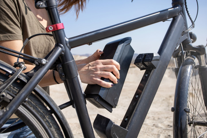
The operating principle of BLDC Motors has already been mentioned (as they are the focus of this article). The most important property of such products is three (or more) stator windings supplied with three phase current supplied by an inverter. The permanent magnet rotor is rotated by an alternating magnetic field generated by the stator windings - thus, by changing the frequency of the signals, the speed of the rotor is controlled. But the frequency will also depend on its current position. The latter is determined by using Hall Sensors built into the motor. Alternatively, a control algorithm (e.g. FOC), whose task is to induce current in phases with an optimal period (based on axis speed data). Controllers for BLDC Motors are an essential component of m.in. actuators bicycles.
Since BLDC Motors rely less on mechanical components (brushes) than conventional ones - they are characterized by lower risk of failure. Their important feature is also lower energy loss (i.e. better efficiency). What's more, allow precise control of speed, which is an important feature in applications such as industrial machinery, robots, drones or fans. Last, but no less important advantage, is the compact design and relatively light weight.
In connection with such favorable characteristics, in addition to the applications mentioned, bLDC Motors are also used in power tools (e.g. screwdrivers), automotive applications (ABS systems, throttle control), electric vehicles (mowers, scooters, bicycles, cars, boats), actuators in robotics and Industrial Robotics.
The growing popularity of micromobility vehicles, such as electric scooters and ebikes has further contributed to the expansion of BLDC Motors and efficient controllers for them. Together, they make it possible to achieve high fuel (energy) efficiency in an era of increasing environmental awareness among societies. As the global market shifts toward the electrification of transportation, it can be expected, that companies producing advanced controllers will not soon see reduced demand for their solutions.
BLDC Control Module Design
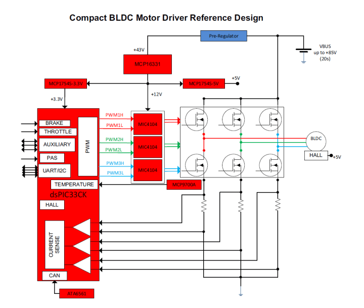
The following is an example design of a compact controller for BLDC Motors. This is a Microchip reference circuit, that illustrates the basic solutions found in modules of this type, as well as the functions, that the manufacturer's components perform in them. The purpose of the controller is to power and control the operation of BLDC/PMSM motors with peak power up to 3 kW and phase currents up to 300A. The supply voltage here can be from 18V to 85V DC, which allows power to be drawn from a variety of typical sources, including a package of lithium-ion cells-ion cells (up to 20 pcs., i.e. 20S Batteries).
Controllers block diagram is as follows: Block diagram of a BLDC controller constructed with Microchip components.
Source: Microchip Technology
dsPIC Microcontrollers
The heart of the digital control system (DSC, Digital Signal Controller) is the dsPIC33CK256MP505 microcontroller operating at 100MIPS (millions of instructions per second). This chip contains, among other things.in. also three internal operational amplifiers, which in this case are used to measure current (bottom left corner of the schematic). In addition, the dsPIC family supports a CAN transceiver, which, in combination with the ATA6561 chip (more on that later), provides native communication with the CAN bus-Bus.
The single-core digital signal controllers of the dsPIC33CK family are built for applications requiring real-time data processing, and therefore primarily in control and protection circuits, as described in the video below:
High-performance chips feature extended registers, through reduced interrupt latency. In addition, they have a number of integrated peripherals, as well as new instructions to natively support DSP (digital signal processing) operations. Digital Signal Processing). The speed of code execution has also been improved here, (Digital Signal Processing), which allows the microcontroller to execute complex control loops in real time.
These chips are only available in SMD formats: TQFP48 and UQFN48. For prototyping purposes, Microchip has prepared the DM330017 development kits-3. Importantly, these microcontrollers feature wide thermal tolerance (even from -40°C to 145°C), allowing them to be used in harsh environmental conditions, which are often found in motor control systems. All of these products are available in the TME catalog.
CAN Bus Transceiver
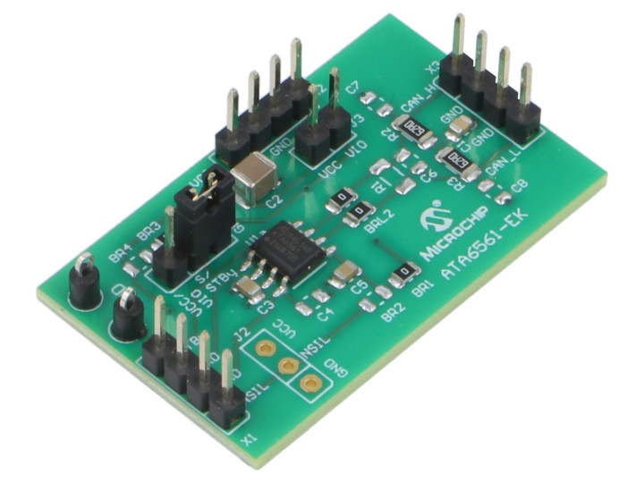
The CAN Interfaces (from Controller Area Network) allows system components to communicate via a two-wire bus. In the circuit described here, this connection is made using a high-speed transciver in the form of ATA6561 integrated circuits. The development board with the ATA6561 chip facilitates the construction of prototypes.
The ATA6561 family chips are CAN transceivers, which provide the connection between the microcontroller and the physical bus. These elements are designed for fast (up to 5Mbps) transmission, necessary e.g. in automotive applications. They offer the ability to transmit and receive differential signals from/through a microcontroller supporting a CAN interface (direct connection). They feature high electromagnetic compatibility (EMC) and electrostatic discharge (ESD) resistance. In addition, they behave passively in case of power loss, without causing interference on the bus. Combined with specialized safety features (fail safe), this makes the ATA6561 chips an excellent choice for all types of CAN networks, especially in systems requiring low power consumption and the option of waking up the component via an external instruction sent through the interface.
Inverter
A key component in controlling BLDC Motors is the Three Phase Inverter, which provides large currents to power the actuator according to the low-voltage signals received from the microcontroller (central part of the block diagram). Here such a circuit has been implemented using six high-performance MOSFET transistors with very low (max. 1,7 mΩ) resistance in the conducting state (parameter RDS(ON), i.e. Drain-Source Resistance when On), which allows handling high phase currents without excessive conduction losses (and system overheating). Transistors operation is controlled by MIC4104 Controllers. Typically, a BLDC Motors has 3 power cords, one for each phase.
MIC4104 are high-speed, synchronous MOSFET transistors drivers. They deliver current up to 2A (max. source current-3A). They are also characterized by very short turn-on (24ns) and turn-off (6ns) times, i.e. dropping of the control signal. These circuits are implemented in the form of a half bridge (the so-called. H bridge).
The MIC4104 circuit is realized according to TTTL parameters, i.e. logic thresholds are<0,8V DC for logical "0", while >2,0V for "1". The high-speed, low-power switch circuit provides clean signal transitions at the output. MIC4104 is designed so that the circuit is not susceptible to power supply noise and rapid voltage changes. Under-voltage protection has been implemented on both the low side, and high side. The MIC4104 also features a wide range of supply voltages (from 5,5V to 16V DC). The low voltage allows longer operation in battery-powered devices. The gate control voltage is set by the circuit at the VDD line level, minimizing power loss.
Alternatively, a newer circuit specialized for BLDC motor applications can be used here, e.g., from the ATA6847 family (these products are currently available from TME as special-order items). These circuits feature, among other things, a wider operating voltage range (3…48V DC).
Transistors
Transistors used in the inverter are MOSFET components: AOTL66912. They are components in SMD enclosures. The gate control circuit controls the rate of voltage rise, ensuring regular, oscillation-free switching on the supply lines (voltages up to 85V and peak currents up to 150A, peak).
Temperature Monitoring
To ensure optimal component temperature, the presented controller circuit requires the use of a heat sink to dissipate heat from the transistors. Heatsinks temperature must be continuously monitored using the built-in MCP9700A temperature sensor. The circuit converts the temperature into an analog voltage (built-in thermistor).
Such an inexpensive and energy-efficient sensor has an accuracy of ±2°C from 0°C to 70°C with a typical current consumption of just 6µA. Unlike resistive sensors, such as classic thermistors, the MCP9700A linear array requires no additional components, which simplifies design and reduces costs.
Operation of the MCP9700A sensor in a circuit, whose purpose is continuous temperature monitoring, is demonstrated in the video:
The output pin of the sensor (VOUT) can be directly connected to the input of the analog-to-digital converter (ADC) of the microcontroller-digital converter (ADC) of the microcontroller. The temperature coefficient of the MCP9700A is calibrated in such a way, to provide a resolution of 1°C/bit at the 8 bit A/D converter and voltage-bit A/D converter and a reference voltage of 2,5V or 5V. For a 12-bit with a reference voltage of 4,096V, a resolution is obtained 0,1°C/bit. The system provides an economical solution for applications, where measurement of relative temperature change is required.
It is worth mentioning here, that the MCP9700A is a compact chip, available in both classic TO92 enclosures, as well as SMD versions: SC70 and SOT23. The full range of temperatures measured by the sensor extends from -40°C to 125°C.
Supply Circuit
Note, that in the circuit presented here, the components operate using three different power supply voltages. For the gate controllers it is 12V DC, for the microcontroller (DSC controller) 3,3V DC, while the Hall sensor installed in the example motor requires 5V DC. What's more: in order to broaden the application range of the module and adapt it to typical power supply methods found in different types of electrical devices, it was assumed, that the range of acceptable input voltages here will be from 12V to 28V. To realize such a power supply circuit,two types of voltage stabilizers were used: MCP16331 and MCP1754.
Converters MCP16331 (12V DC line)
The MCP16331 chip is an integrated step-up DC/DC Converters-down with high efficiency (up to 96%). Microchip manufactures it in popular Enclosures 6-pin (SOT23) and 8\Npins (2x3mm)-pin (2x3mm, TDFN). It can operate with input voltages up to 50V and operates at a fixed frequency. The chip is equipped with a number of important functionalities: high side switch (high side switch), peak current control (peak current mode), internal compensation, current limiter, thermal protection. Only a few external components need to be connected to this integrated power supply, e.g. resistor divider, which is used to determine the output voltage value. MCP16331 can deliver up to 500mA, by regulating the output voltage in the range from 2V to 24V DC.
The impressive efficiency of the converter is due to the current-limited, high-speed N-type MOSFET transistors with very low resistance. High switching frequency allows the use of small filter elements, which translates into a compact size of the whole system. Integrated Peak Current Mode architecture provides precise output voltage regulation, even during rapid changes on the input line or load side.
EN input (enable) is used to turn the chip on and off. In the off state, it draws only a few microamperes of current, which is beneficial in applications requiring power management, load distribution, and above all - battery-powered devices. The EN lead is internally pulled to the power line, so the use of this pin is not required (it will be in steady state, switching on the inverter).
Regulators MCP1754 (lines 3,3V and 5V DC)
MCP1754/MCP1754S are a family of low dropout (LDO) type voltage regulators (Low Dropout) made with CMOS technology. These chips can deliver current up to 150mA, while consuming only 56μA of resting current (typical). They are therefore particularly useful in portable applications, where low power loss is important. The input voltage range is from 3,6V to 16V DC, making these components ideal for: devices powered by 4 to 6 battery cells (e.g. AA or AAAtype, etc.); mobile applications with a power supply of approx. 12V DC, devices powered by one to three cells Li -Ion.
Summary
With small dimensions, low cost and high performance, the presented design of a compact BLDC Motors Controller can become the basis for many solutions. And although the circuit can be modified in many places, even in this form, it will perform excellently in modern applications in the so-called "green" industry. e-mobility, i.e. electric scooters or bicycles. Additionally, it can also be used to power BLDC Motors in high-powered drones and unmanned aerial vehicles (UAVs).
In conclusion, let's emphasize again, that all Microchip components required for the circuit are available from the TME catalog and shipped directly from our warehouses. When selecting controller components, it is worth remembering, that electric scooter actuators and controllers sometimes have to cope with the harshest weather conditions.Text prepared by Transfer Multisort Elektronik Sp. z o.o.
https://www.tme.eu/en/news/about-product/page/65038/microchip-components-and-bdlc-motor-control/


Discussion (0 comments)